


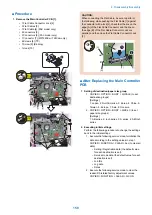


■ Procedure
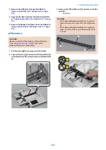
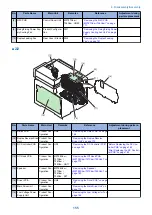
1. Remove the Main Controller PCB [1].
• 1 Flat Cable Connector Lock [2]
• 3 Flat Cables [3]
• 1 Flat Cable [4] (FAX model only)
• 6 Connectors [5]
• 2 Connectors [6] (FAX model only)
• 1 Connector [7] (MF728Cdw / 724Cdw only)
• 6 Screws [8] (TP)
• 1 Screw [9] (Binding)
• 1 Hook [10]
[5]
[5]
[6]
[4]
[1]
[3]
[3]
[5]
[8]
[8]
[2]
7x
13x
[5]
[5]
[7]
[9]
[10]
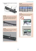
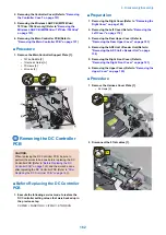
CAUTION:
When connecting the Flat Cable, be sure to perform
the following; while pushing the Flat Cable [1] against
the connector with a lock [2], check that the line on the
edge [A] of the Flat Cable Connector and the line on
the edge [B] of the Flat Cable Connector Lock are
parallel, and then close the Flat Cable Connector Lock
[3].
[1]
[3]
[2]
[A]
[B]
■ After Replacing the Main Controller
PCB
1. Setting of destination/paper size group
1. COPIER > OPTION > BODY > LOCALE (to set
destination groups)
[Settings]
1: Japan, 2: North America, 3: Korea, 4: China, 5:
Taiwan, 6: Europe, 7: Asia, 8: Oceania
2. COPIER > OPTION > BODY > SIZE-LC (to set
paper size groups)
[Settings]
1: AB series, 2: Inch series, 3: A series, 4: AB/Inch
series
2. Executing initial settings.
Perform the following procedure to change the settings
back to the initial settings.
1. Execute the following service mode to initialize the
data according to the setting values in step 1.
COPIER > FUNCTION > CLEAR > ALL (to clear all
data)
• Setting / Registration data (the default value
for each destination is set).
• Service mode data (the default value for each
destination is set).
• Job IDs
• Log data
• Dates
2. Execute the following service mode to clear the
reader/DF-related factory adjustment values.
COPIER > FUNCTION > CLEAR > R-CON
4. Disassembly/Assembly
159
Summary of Contents for MF720 Series
Page 1: ...Revision 2 0 MF720 Series Service Manual...
Page 12: ...Product Overview 1 Product Lineups 5 Product Features 7 Specifications 8 Name of Parts 14...
Page 79: ...4 Click Import Export Import 1 2 2 Technical Explanation 71...
Page 103: ...Durable Parts No durable parts is set for this product 3 Periodical Service 95...
Page 104: ...Periodical Services No periodical service is set for this product 3 Periodical Service 96...
Page 232: ...Adjustment 5 Overview 225 Adjustment at Parts Replacement 226...
Page 248: ...Troubleshooting 6 Test Print 241 Trouble shooting items 243 Version Upgrade 244 Debug Log 248...
Page 258: ...Error Jam Alarm 7 Outline 251 Error Codes 252 Jam Code 257...
Page 267: ...Service Mode 8 Overview 260 COPIER 264 FEEDER 300 FAX 302 TESTMODE 308...
Page 322: ...APPENDICES Service Tools 315 General Circuit Diagram 316 Print Sequence 317 Backup Data 318...