Chapter 2
2-5
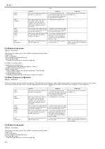
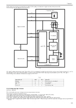
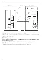
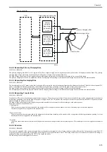
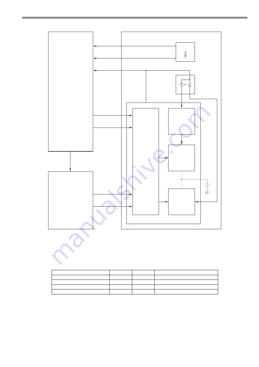
In this control, the laser driver turns on/off the laser diode (LD) according to the laser control signal sent from the engine controller.
The following is the circuit diagram of the laser control.
F-2-5
The engine controller sends the laser control signal (CNT0, CNT1) for changing the operation mode of the laser to the logic circuit in the laser driver IC, as well as
the video signal (VD0, /VD0) for image formation. The laser driver IC executes laser control according to the combination of the CNT0, CNT1 signals.
The following is the combination of the laser control signal (CNT0, CNT1).
T-2-3
2.3.2.2 Horizontal Sync Control
0019-3464
LBP3100 / LBP3010B
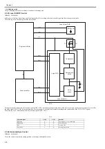
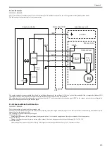
This is the control to adjust the writing position in the image horizontal direction.
The following is the details of control procedure.
1) The engine controller controls the laser control signal during unblanking (*) to emit the laser diode (LD) forcibly.
2) The BD PCB exists on the scanning route of the laser beam, which is sent to the BD PCB.
3) The BD PCB detects this laser beam, creates BD input signal (/BDI) and sends it to the engine controller.
4) The engine controller creates horizontal sync signals (/BD) based on /BDI signal and sends the /BD signal to the main controller.
5) When /BD signal is input, the main controller outputs the video signal (VD0, /VD0) to the engine controller to adjust the writing position in image horizontal
direction.
Operation mode
CNT0
CNT1
Remarks
Discharge
L
L
The capacitor (C1) is discharged.
Data output
H
H
At normal print
APC
H
L
At using APC
Forced OFF
L
H
At using image mask
Engine controller
Main controller
Laser driver PCB
Laser driver IC
BD Sensor
LD
PD
C1
+3.3V
/BDI
+5V
CNT1
CNT0
VOD
/VOD
Sample hold
circuit
Drive
circuit
Comparator
Logic PCB
/BD
Summary of Contents for LBP6000 Series
Page 1: ...Sep 8 2010 Service Manual LBP6000 6018 3010 3100 3150 Series...
Page 2: ......
Page 6: ......
Page 12: ...Contents...
Page 13: ...Chapter 1 PRODUCT DESCRIPTION...
Page 14: ......
Page 16: ......
Page 28: ......
Page 29: ...Chapter 2 TECHNICAL REFERENCE...
Page 30: ......
Page 74: ......
Page 75: ...Chapter 3 DISASSEMBLY AND ASSEMBLY...
Page 76: ......
Page 119: ...Chapter 4 MAINTENANCE AND INSPECTION...
Page 120: ......
Page 122: ......
Page 126: ......
Page 127: ...Chapter 5 TROUBLESHOOTING...
Page 128: ......
Page 130: ......
Page 137: ...Chapter 6 APPENDIX...
Page 138: ......
Page 140: ......
Page 144: ......
Page 145: ...Sep 8 2010...
Page 146: ......

