Chapter 2
2-4
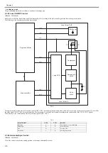
8) When the Four-faced mirror rotates at a constant speed, the laser beam on the Photosensitive drum is scanned on the Photosensitive drum at a constant speed.
9) When the Photosensitive drum rotates at a constant speed and the laser beam is scanned on the Photosensitive drum at a constant speed, latent images are formed
on the Photosensitive drum.
2.3.1.2 Overview
0025-1138
LBP6000 / LBP6000B
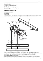
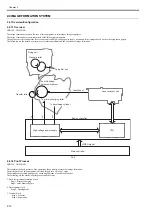
The laser Exposure system forms static latent images on the photosensitive drum according to the VIDEO signals sent from the main controller, and is comprised
of the laser driver and scanner motor, etc. There are controlled by the engine controller. The following is the outline of the laser Exposure system.
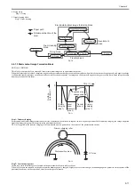
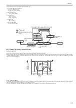
F-2-4
The operational sequence of the laser scanner unit is described below.
1) When the Main controller sends print instruction command, the Engine controller rotates the Four-faced mirror, causing the Scanner motor to rotate.
2) When the Scanner motor starts to rotate, the Engine controller emits the laser forcibly using the Laser control signal, causing the Engine controller to start rotation
control for the Scanner motor.
3) The Engine controller controls to keep a constant speed of rotation of the Scanner motor using the Scanner motor speed control signal.
4) After the rotation speed of the Scanner motor reaches its target, the Main controller sends VIDEO signals to the Laser driver PCB.
5) The Laser driver emits laser diode according to these signals.
6) The laser beam passes through the collimator lens and the cylindrical lens and enters the Four-faced mirror rotating at a constant speed.
7) The laser beam reflected by the Four-faced mirror is focused on the Photosensitive drum via the image-forming lens at the front of the Four-faced mirror.
8) When the Four-faced mirror rotates at a constant speed, the laser beam on the Photosensitive drum is scanned on the Photosensitive drum at a constant speed.
9) When the Photosensitive drum rotates at a constant speed and the laser beam is scanned on the Photosensitive drum at a constant speed, latent images are formed
on the Photosensitive drum.
2.3.2 Controlling the Laser Activation Timing
2.3.2.1 Laser ON/OFF Control
0019-3461
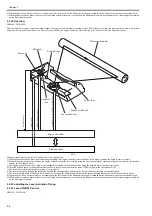
LBP3100 / LBP3010B
Laser unit
Scanner motor unit
Four-faced mirror
Syndrical lens
Photosensitive drum
Engine Controller
BD INPUT signal
VIDEO signal
LASER CONTROL signal
SCANNER MOTOR SPEED CONTROL signal
Main controller
Forcus lens
BD sensor
Collimator
lens
Summary of Contents for LBP6000 Series
Page 1: ...Sep 8 2010 Service Manual LBP6000 6018 3010 3100 3150 Series...
Page 2: ......
Page 6: ......
Page 12: ...Contents...
Page 13: ...Chapter 1 PRODUCT DESCRIPTION...
Page 14: ......
Page 16: ......
Page 28: ......
Page 29: ...Chapter 2 TECHNICAL REFERENCE...
Page 30: ......
Page 74: ......
Page 75: ...Chapter 3 DISASSEMBLY AND ASSEMBLY...
Page 76: ......
Page 119: ...Chapter 4 MAINTENANCE AND INSPECTION...
Page 120: ......
Page 122: ......
Page 126: ......
Page 127: ...Chapter 5 TROUBLESHOOTING...
Page 128: ......
Page 130: ......
Page 137: ...Chapter 6 APPENDIX...
Page 138: ......
Page 140: ......
Page 144: ......
Page 145: ...Sep 8 2010...
Page 146: ......

