HTTP://WWW.FIXCLUB.COM.CN
Chapter 2
2-6
2.4 IMAGE FORMATION SYSTEM
2.4.1 Overview/Configuration
2.4.1.1 Construction
0008-0101
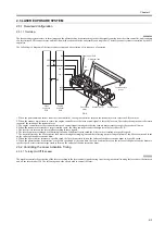
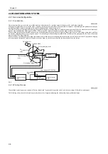
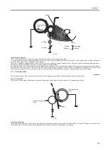
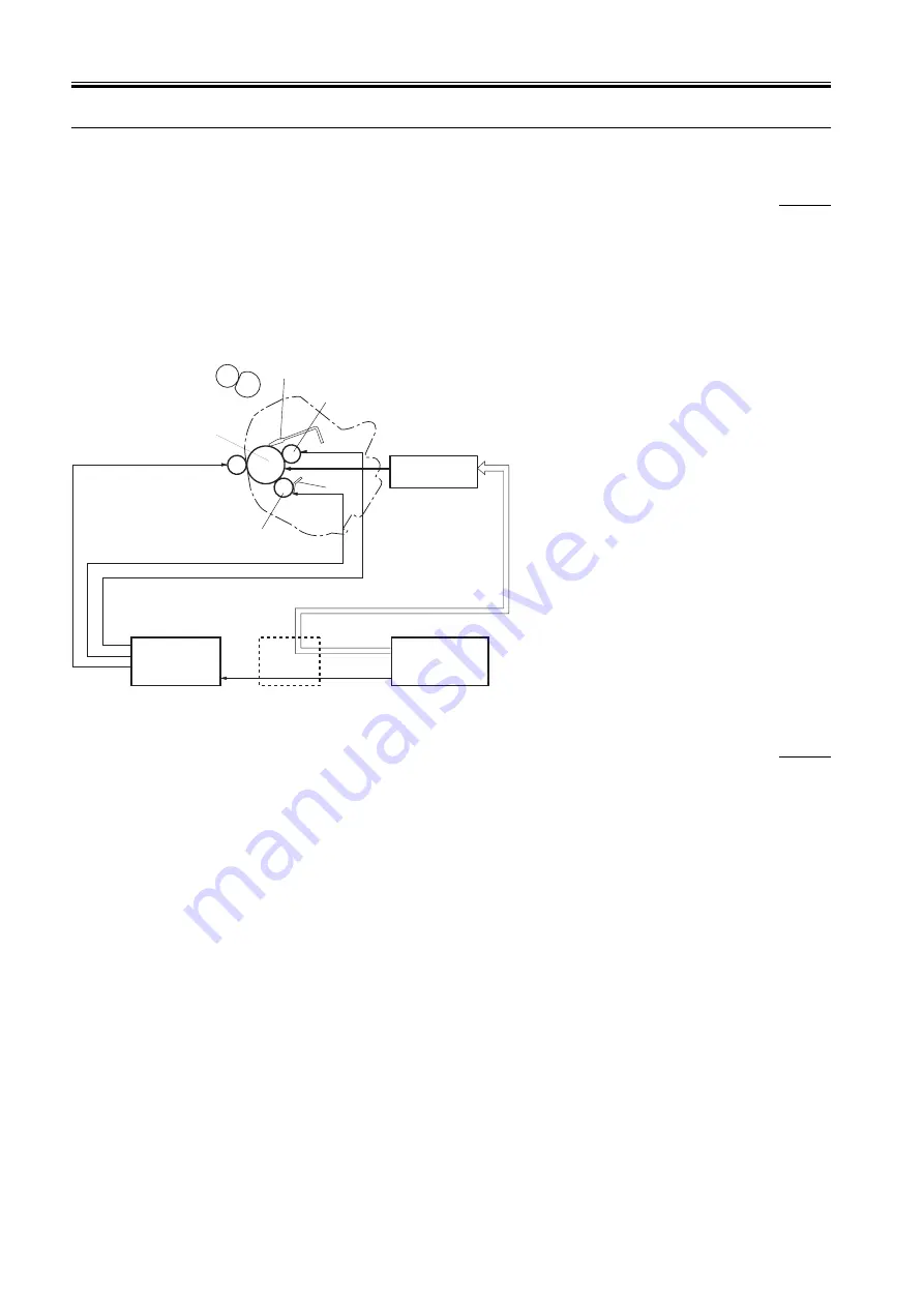
The image formation system is the core of the machine, and consists of a cartridge, transfer charging roller, and fixing assembly.
When a print command arrives from the video controller, the engine controller drives the main motor in response, thus turning on the photosensitive drum,
developing cylinder, primary charging roller, transfer charging roller, and pressure roller.
Thereafter, the primary charging roller charges the surface of the photosensitive drum to a uniform negative potential; then, the machine scans a laser beam
that has been modulated by video signals (VDO, /VDO) across the surface of the photosensitive drum to form a latent image.
When a latent image has been formed on the surface of the photosensitive drum, the developing cylinder turns it into a visible image using toner, and then
the transfer charging roller moves it to print paper. The toner image is then fused permanently into the fibers of the print paper by the work of heat and
pressure inside the fixing assembly.
When all is done, the cleaning blade scrapes the residual toner off the surface of the photosensitive drum for collection as waste toner. The primary charging
roller once again charges the surface of the photosensitive drum to a uniform potential for the formation of the next image.
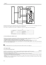
F-2-5
2.4.1.2 Printing Process
0008-0102
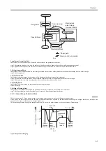
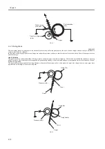
The machine's printing process consists of 5 major blocks and 7 sequential steps at the end of which a toner image is formed on print paper.
The following shows these blocks and steps with reference to a diagram indicating the relationship among individual steps:
Laser/
scanner unit
Cleaning blade
Photosensitive
drum
Primary charging roller
Cartridge
Blade
Developing cylinder
Transfer charging
roller
Laser beam
Fixing film unit
Engine controller
PCB
print
command
Video signals (VDO, /VDO)
Intermediate
PCB
PR1
TRS
DEV
Video controller
PCB
Summary of Contents for LBP-3000
Page 1: ...H T T P W W W F I X C L U B C O M C N Mar 10 2005 Service Manual LBP3000 2900 Series LBP2900 ...
Page 2: ...H T T P W W W F I X C L U B C O M C N ...
Page 6: ...H T T P W W W F I X C L U B C O M C N ...
Page 12: ...H T T P W W W F I X C L U B C O M C N Contents ...
Page 13: ...H T T P W W W F I X C L U B C O M C N Chapter 1 PRODUCT DESCRIPTION ...
Page 14: ...H T T P W W W F I X C L U B C O M C N ...
Page 16: ...H T T P W W W F I X C L U B C O M C N ...
Page 23: ...H T T P W W W F I X C L U B C O M C N Chapter 2 TECHNICAL REFERENCE ...
Page 24: ...H T T P W W W F I X C L U B C O M C N ...
Page 44: ...H T T P W W W F I X C L U B C O M C N Chapter 2 2 18 ...
Page 51: ...H T T P W W W F I X C L U B C O M C N Chapter 3 DISASSEMBLY AND ASSEMBLY ...
Page 52: ...H T T P W W W F I X C L U B C O M C N ...
Page 87: ...H T T P W W W F I X C L U B C O M C N Chapter 3 3 33 F 3 161 ...
Page 88: ...H T T P W W W F I X C L U B C O M C N ...
Page 89: ...H T T P W W W F I X C L U B C O M C N Chapter 4 MAINTENANCE AND INSPECTION ...
Page 90: ...H T T P W W W F I X C L U B C O M C N ...
Page 92: ...H T T P W W W F I X C L U B C O M C N ...
Page 98: ...H T T P W W W F I X C L U B C O M C N ...
Page 99: ...H T T P W W W F I X C L U B C O M C N Chapter 5 TROUBLESHOOTING ...
Page 100: ...H T T P W W W F I X C L U B C O M C N ...
Page 102: ...H T T P W W W F I X C L U B C O M C N ...
Page 107: ...H T T P W W W F I X C L U B C O M C N Chapter 6 APPENDIX ...
Page 108: ...H T T P W W W F I X C L U B C O M C N ...
Page 110: ...H T T P W W W F I X C L U B C O M C N ...
Page 117: ...H T T P W W W F I X C L U B C O M C N Mar 10 2005 ...

