


CHAPTER 6
cause Step
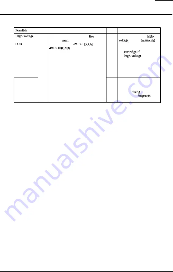
Check
Result
Procedure
7
Perform a test print. About
seconds YES
Check whether the
power supply
after the
motor starts, does the
contact
voltage between
and
good contact with the
(Developing
on the DC controller
developing bias contact of
bias)
PCB become about 0.76 VDC?
the
It Is. replace
the
power
supply PCB. If the problem
persists after replacing the
PCB. check by using the
laser malfunction diagnosis
flowchart in Section III C.
DC controller
PCB
NO
Replace the DC controller
PCB. If the problem persists
after replacing the PCB,
check by
the laser
malfunction
flowchart in Section III C.
6-16
Summary of Contents for LBP-1260
Page 1: ...LBP 1260 SERVICE MANUAL Canon...
Page 35: ...l 29...
Page 36: ...CNAPTER 1 1 30...
Page 63: ...CHAPTER 2 This page intentionally left blank 2 26...
Page 88: ......
Page 139: ......
Page 153: ...ER 6 This page intentionally left blank 6 7...
Page 157: ...CHAPTER 6 o r J20 J215 I u IC201 El IC202 TB201 J214 J213 Fi m 6 7 6 11...
Page 193: ...This page intentionally left blank 6 4 7...
Page 194: ...CHAPTER 6 A Switches 1 I Figure 11 6 46...
Page 196: ...B Sensore and Sotenoids Flgurc 6 12 6 50...
Page 198: ...CHAPTER 6 C Motors and Others Figure 6 13 6 52...
Page 200: ...CEtApTER 6 D PC Boards Figure 6 14 6 54...
Page 202: ...E Connectors Figure 6 16 6 56...
Page 203: ...Figure 6 16 6 57...
Page 210: ...no VIDEO si ml VS Q VERTICAL SYNC REQUEZT signal VSYNC VERTICAI SYNC A 4...
Page 212: ...IV DC CONTROLLER DC controller 112 fi 6 4 3 I 2 I 1 A 6...
Page 213: ...DC controller 2 2 iy j A 7...
Page 215: ...Pick up motor driver 2 2 SENSOR PCB J602 0 A pA J602 bB1 pA J602 om pB I 24UA IPlO 1 SD A 9...
Page 216: ...D I R 7...
Page 217: ...VII PAPER FEEDER DRIVER 3 I 1 A 11...