


Chapter 7
7-12
Door Open Jam
The door is opened when paper to be printed is in the paper feed path.
7.3 Cassette Pick-Up Unit
7.3.1 Overview
0020-4134
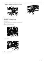
The paper picked up from the cassette is fed to the registration roller using the vertical path roller driven by the main motor (M204). The registration roller is not
rotating when paper reaches there, so an arch is formed at the leading of the paper to prevent skewing. The DC controller PCB turns on the registration clutch
(CL203) at the prescribed timing to transfer the main motor rotation to the registration roller, thus feeding the paper to the delivery tray through the transfer, sepa-
ration, fixing, and delivery assemblies.
F-7-15
7.3.2 Cassette Pickup Operation
0020-4135
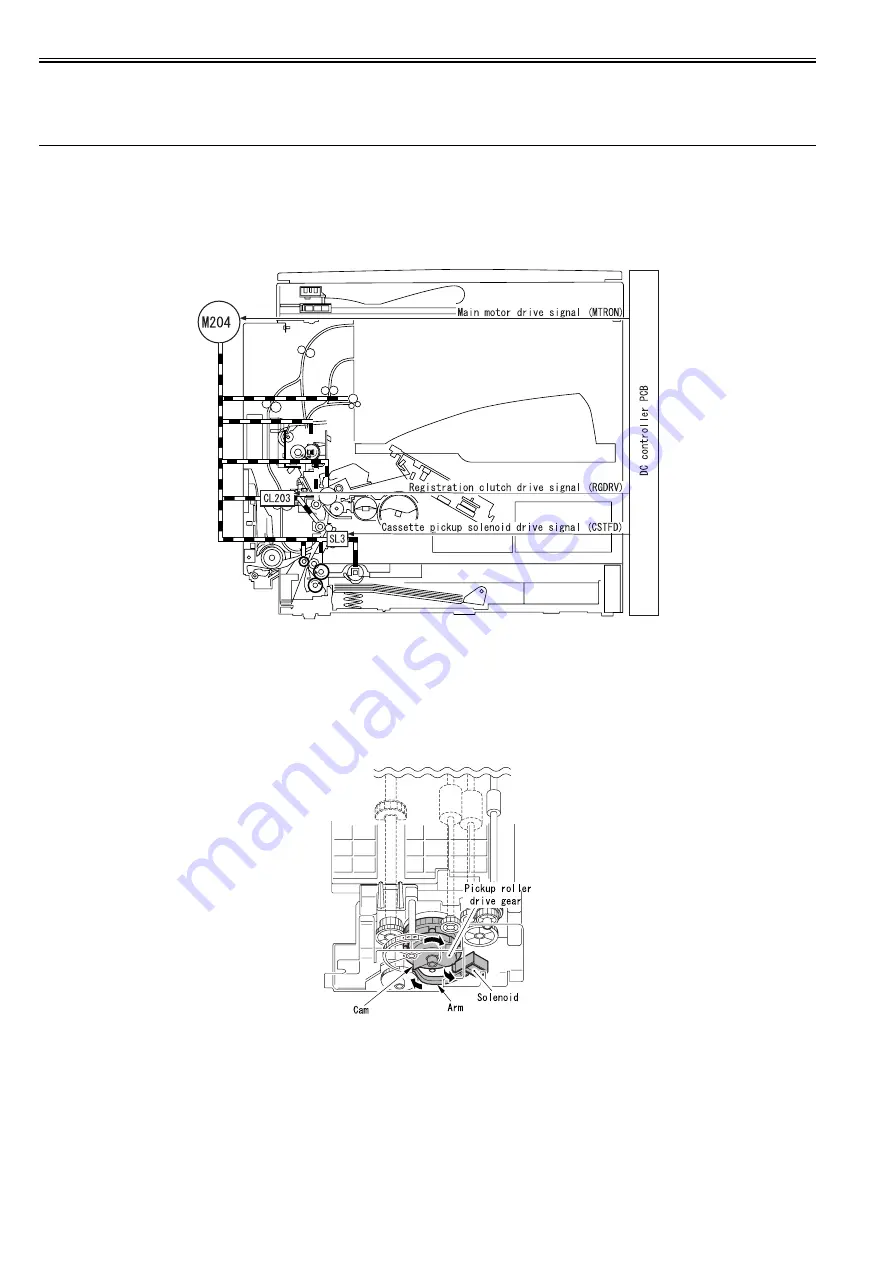
Rotation of the pickup roller is controlled by the pickup roller drive gear, which transfers the drive power of the main motor (M204) to the pickup roller drive shaft,
and the cassette pickup solenoid (SL202). When the main motor starts rotating, the interlocked relay gear also starts rotating. At this time, the pickup roller drive
gear is not driven because its toothless portion is positioned at the relay gear and therefore these gears are not engaged with each other.
1) The DC controller PCB issues a cassette pickup solenoid drive signal (CSTFD). When the solenoid is turned on, the control arm pushes the cam to rotate the
pickup roller drive gear slightly.
F-7-16
Summary of Contents for iR2422 series
Page 1: ...May 12 2014 Service Manual iR2422 2420 2320 2318 Series...
Page 2: ......
Page 6: ......
Page 16: ...Contents...
Page 17: ...Chapter 1 Introduction...
Page 18: ......
Page 20: ......
Page 50: ......
Page 51: ...Chapter 2 Installation...
Page 52: ......
Page 54: ......
Page 58: ...Chapter 2 2 4 7 Left cover front 15 Right cover upper 8 Manual feed tray 16 Right cover lower...
Page 62: ...Chapter 2 2 8 8 Manual feed tray 16 Right cover lower...
Page 64: ...Chapter 2 2 10 8 Manual feed tray 16 Right cover lower...
Page 89: ...Chapter 2 2 35...
Page 90: ......
Page 91: ...Chapter 3 Main Controller...
Page 92: ......
Page 94: ......
Page 102: ......
Page 103: ...Chapter 4 Original Exposure System...
Page 104: ......
Page 135: ...9 Remove the reader heater left 1 Connector 2 1 pc Screw 3 1 pc F 4 73 2 3 1...
Page 136: ......
Page 137: ...Chapter 5 Laser Exposure...
Page 138: ......
Page 140: ......
Page 148: ...Chapter 5 5 8...
Page 149: ...Chapter 6 Image Formation...
Page 150: ......
Page 152: ......
Page 165: ...Chapter 7 Pickup Feeding System...
Page 166: ......
Page 192: ...Chapter 7 7 24...
Page 193: ...Chapter 8 Fixing System...
Page 194: ......
Page 196: ......
Page 207: ...Chapter 9 External and Controls...
Page 208: ......
Page 229: ...Chapter 10 Maintenance and Inspection...
Page 230: ......
Page 232: ......
Page 235: ...Chapter 11 Standards and Adjustments...
Page 236: ......
Page 238: ......
Page 240: ...Chapter 11 11 2...
Page 241: ...Chapter 12 Correcting Faulty Images...
Page 242: ......
Page 244: ......
Page 256: ......
Page 257: ...Chapter 13 Self Diagnosis...
Page 258: ......
Page 260: ......
Page 269: ...Chapter 14 Service Mode...
Page 270: ......
Page 272: ......
Page 287: ...Chapter 15 Upgrading...
Page 288: ......
Page 290: ......
Page 295: ...Chapter 16 Service Tools...
Page 296: ......
Page 298: ......
Page 300: ......
Page 301: ...Chapter 17 Backup Data...
Page 302: ......
Page 303: ...Contents Contents 17 1 Backup Data 17 1...
Page 304: ......
Page 306: ......
Page 307: ...May 12 2014...
Page 308: ......


