Chapter 13
13-11
13.5
Electrical Components
13.5.1
After Replacing the
HDD
0007-8275
iR2270 / iR2870 / iR3570 / iR4570 / iR3530
1) Format the HDD.
Start up the machine in safe mode (i.e., while holding
down the 2 and 8 keys, turn on the main power).
Using the HD format function of the SST, format all
partitions ($); for details, see the descriptions given
for upgrading.
2) Download the system software.
Using the SST, download the following:
LANGUAGE, RUI, PS-FRONT, OCR dictionary,
SSL coding key, SSL CA certificate, MEAP
content.
Keep in mind that the machine may take about 5 min
to start up after downloading.
13.5.2
After Replacing the
DC Controller PCB
0007-4922
iR2270 / iR2870 / iR3570 / iR4570 / iR3530
- Before replacing the DC controller PCB, print out
the latest P-PRINT page.
C O P I E R > F U N C T I O N > M I S C - P > P -
1) Using the SST, download the latest system
software.
2) Using the following service mode item, initialize
the memory of the DC controller PCB:
COPIER>FUNCTION>CLEAR>DC-CON
3) Using the following service mode items, enter the
values indicated on the P-PRINT page:
- COPIER>ADJUST>LASER>
LA-DELAY/ LA-
OFF/ POWER
-
COPIER>ADJUST>DEVELOP>
DE-OFST
-
COPIER>ADJUST>BLANK>
BLANK-T/
BLANK-B
-
COPIER>ADJUST>HV-RPRI>
OFST-DC/ OFST-
AC
-
COPIER>ADJUST>HV-TR all items under
- COPIER>ADJUST>FEED-ADJ all items under
- COPIER>ADJUST>CST-ADJ all items under
- COPIER>ADJUST>FIXING all items under
- COPIER>ADJUST>MISC all items under
4) Execute the following service mode items:
- COPIER > FUNCTION > DPC > D-GAMMA
13.5.3
After Replacing the
Main Controller PCB
0007-5188
iR2270 / iR2870 / iR3570 / iR4570 / iR3530
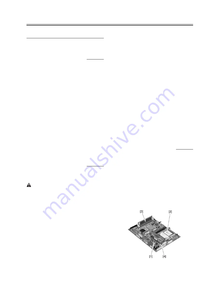
If you are replacing the main controller PCB, be sure
to transfer the following components from the
old to new PCB:
[1]
boot ROM
[2]
HDD
[3]
image memory (SDRAM)
[4]
counter memory PCB
F-13-23
Summary of Contents for iR2270 Series
Page 1: ...Jan 31 2005 Service Manual iR4570 3570 2870 2270 Series ...
Page 2: ......
Page 6: ......
Page 29: ...Chapter 1 Introduction ...
Page 30: ......
Page 106: ......
Page 107: ...Chapter 2 Installation ...
Page 108: ......
Page 110: ......
Page 132: ...system setup network Ethernet driver setup auto detect ...
Page 152: ...F 2 94 3 2 3 1 ...
Page 153: ...Chapter 3 Basic Operation ...
Page 154: ......
Page 156: ......
Page 162: ......
Page 163: ...Chapter 4 Main Controller ...
Page 164: ......
Page 204: ......
Page 205: ...Chapter 5 Original Exposure System ...
Page 206: ......
Page 253: ...Chapter 6 Laser Exposure ...
Page 254: ......
Page 256: ......
Page 270: ......
Page 271: ...Chapter 7 Image Formation ...
Page 272: ......
Page 276: ......
Page 289: ...F 7 13 1 2 3 4 ...
Page 348: ......
Page 349: ...Chapter 8 Pickup Feeding System ...
Page 350: ......
Page 356: ......
Page 511: ...Chapter 9 Fixing System ...
Page 512: ......
Page 556: ......
Page 557: ...Chapter 10 External and Controls ...
Page 558: ......
Page 562: ......
Page 632: ......
Page 633: ...Chapter 11 MEAP ...
Page 634: ......
Page 636: ......
Page 641: ...Chapter 12 Maintenance and Inspection ...
Page 642: ......
Page 644: ......
Page 680: ......
Page 681: ...Chapter 13 Standards and Adjustments ...
Page 682: ......
Page 684: ......
Page 703: ...Chapter 14 Correcting Faulty Images ...
Page 704: ......
Page 754: ...T 14 28 Notation Description VR201 for factory use ...
Page 755: ...Chapter 15 Self Diagnosis ...
Page 756: ......
Page 758: ......
Page 841: ...Chapter 16 Service Mode ...
Page 842: ......
Page 844: ...Contents 16 8 1 COPIER 16 102 16 8 1 1 Copier List 16 102 ...
Page 953: ...Chapter 17 Upgrading ...
Page 954: ......
Page 956: ......
Page 962: ...F 17 4 HDD Boot ROM Flash ROM System Software ...
Page 968: ...F 17 12 ...
Page 998: ...Chapter 17 17 42 F 17 56 2 Select the data to download F 17 57 3 Click Start ...
Page 1001: ...Chapter 18 Service Tools ...
Page 1002: ......
Page 1003: ...Contents Contents 18 1 Special Tools 18 1 18 2 Oils and Solvents 18 2 ...
Page 1004: ......
Page 1007: ...Jan 31 2005 ...
Page 1008: ......


