


Chapter 13
13-1
13.1
Image Adjustments
13.1.1
Standards for Image
Position
0007-4812
iR2270 / iR2870 / iR3570 / iR4570 / iR3530
A print made at a magnification of 100% must meet
the following standards for image margin/non-image
width:
- Margin Along the Leading Edge
F-13-1
- Left/Right Image Margin
F-13-2
- Leading Edge Non-Image Width
F-13-3
- Left/Right Non-Image Width
F-13-4
13.1.2
Adjusting the Image
Position
0007-4813
iR2270 / iR2870 / iR3570 / iR4570 / iR3530
Using the source of paper indicated, make 10 prints
each to see if the image margin and the non-image
margin are as indicated:
[1] Cassettes
[2] Manual feed tray
[3] Side paper deck
If not as indicated, adjust the image position as
follows:
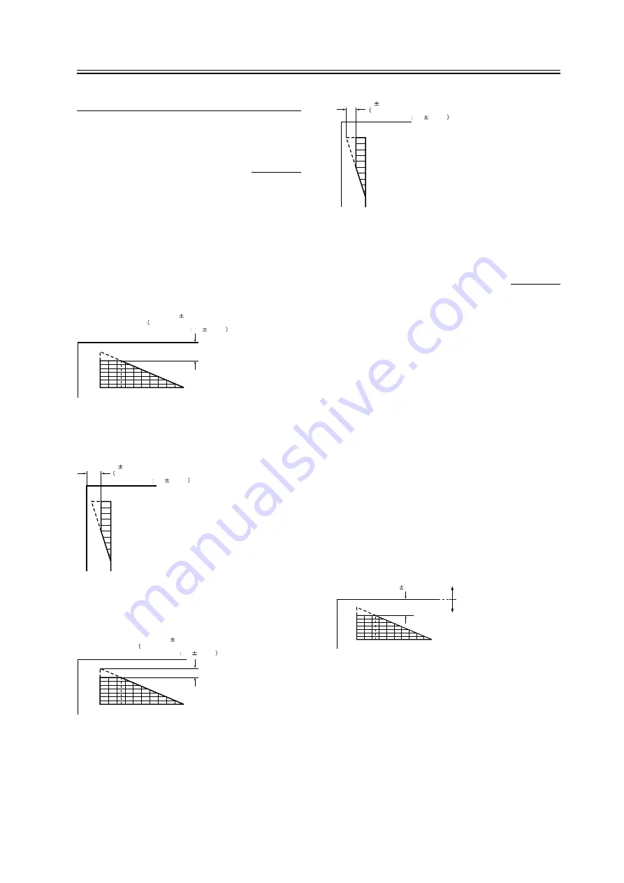
1.Adjusting the Leading Edge Image Margin (1st
side)
Adjust the registration in service mode:
COPIER > ADJUST > FEED-ADJ > REGIST
F-13-5
2. Adjusting the Left/Right Image (1st side)
Mechanical Horizontal Registration Adjustment
3. Adjusting the Leading Edge Image Margin (2nd
side)
Adjust the registration in service mode:
2
5
4 6 8 10 12 14 16 18 20
0
2.5
1.5mm
2nd side of double-sided copy
2.5
2.0mm
10
8
6
5
4
2
0
2.5
1.5mm
2nd side of double-sided copy
2.5
2.0mm
2
5
4 6 8 10 12 14 16 18 20
0
2.5
1.5mm
2nd side of double-sided copy
2.5
1.5mm
10
8
6
5
4
2
0
2.5
1.5mm
2nd side of double-sided copy
2.5
1.5mm
Paper
leading edge
Decrease the REGIST setting.
(a decrease of '10' will
increase the margin by 1 mm)
Increase the REGIST setting.
(an increase of '10' will
increase the margin by 1 mm)
2
5
4 6 8 10 12 14 16 18 20
0
1st side of copy : 2.5 1.5mm
Summary of Contents for iR2270 Series
Page 1: ...Jan 31 2005 Service Manual iR4570 3570 2870 2270 Series ...
Page 2: ......
Page 6: ......
Page 29: ...Chapter 1 Introduction ...
Page 30: ......
Page 106: ......
Page 107: ...Chapter 2 Installation ...
Page 108: ......
Page 110: ......
Page 132: ...system setup network Ethernet driver setup auto detect ...
Page 152: ...F 2 94 3 2 3 1 ...
Page 153: ...Chapter 3 Basic Operation ...
Page 154: ......
Page 156: ......
Page 162: ......
Page 163: ...Chapter 4 Main Controller ...
Page 164: ......
Page 204: ......
Page 205: ...Chapter 5 Original Exposure System ...
Page 206: ......
Page 253: ...Chapter 6 Laser Exposure ...
Page 254: ......
Page 256: ......
Page 270: ......
Page 271: ...Chapter 7 Image Formation ...
Page 272: ......
Page 276: ......
Page 289: ...F 7 13 1 2 3 4 ...
Page 348: ......
Page 349: ...Chapter 8 Pickup Feeding System ...
Page 350: ......
Page 356: ......
Page 511: ...Chapter 9 Fixing System ...
Page 512: ......
Page 556: ......
Page 557: ...Chapter 10 External and Controls ...
Page 558: ......
Page 562: ......
Page 632: ......
Page 633: ...Chapter 11 MEAP ...
Page 634: ......
Page 636: ......
Page 641: ...Chapter 12 Maintenance and Inspection ...
Page 642: ......
Page 644: ......
Page 680: ......
Page 681: ...Chapter 13 Standards and Adjustments ...
Page 682: ......
Page 684: ......
Page 703: ...Chapter 14 Correcting Faulty Images ...
Page 704: ......
Page 754: ...T 14 28 Notation Description VR201 for factory use ...
Page 755: ...Chapter 15 Self Diagnosis ...
Page 756: ......
Page 758: ......
Page 841: ...Chapter 16 Service Mode ...
Page 842: ......
Page 844: ...Contents 16 8 1 COPIER 16 102 16 8 1 1 Copier List 16 102 ...
Page 953: ...Chapter 17 Upgrading ...
Page 954: ......
Page 956: ......
Page 962: ...F 17 4 HDD Boot ROM Flash ROM System Software ...
Page 968: ...F 17 12 ...
Page 998: ...Chapter 17 17 42 F 17 56 2 Select the data to download F 17 57 3 Click Start ...
Page 1001: ...Chapter 18 Service Tools ...
Page 1002: ......
Page 1003: ...Contents Contents 18 1 Special Tools 18 1 18 2 Oils and Solvents 18 2 ...
Page 1004: ......
Page 1007: ...Jan 31 2005 ...
Page 1008: ......


