


Chapter 4
4-2
4.2 Disassembly/Reassembly
4.2.1 Disassembly/Reassembly
0016-9451
iPF810 / iPF820
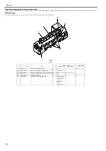
For the procedure for disassembly/reassembly of the components excluding the major components, refer to the parts catalog.
Illustrations in the parts catalog are assigned illustration numbers according to the order in which parts are disassembled.
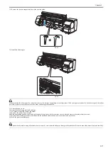
4.3 Points to Note on Disassembly and Reassembly
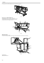
4.3.1 Note on locations prohibited from disassembly
0012-6514
iPF810 / iPF820
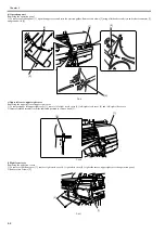
Assemblies that are prohibited from disassembly and their adjustment outside the factory cannot be conducted are indicated by red screws.
Don't never loosen or remove the red screw, because normal operation and print can't be done if it is loosened or removed.
F-4-2
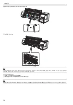
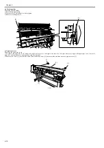
4.3.2 Moving the carriage manually
0020-5644
iPF810 / iPF820
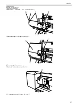
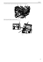
When moving the carriage, hold it by handle [1] shown below.
Move the carriage as required during assembly and disassembly to prevent the carriage from contacting the parts to be removed.
You cannot move the carriage when capping has been performed. Refer to DISASSEMBLY/REASSEMBLY > Points to Notes on Disassembly and Reassembly
> Opening the caps and moving the wiper unit to remove the caps, and then move the carriage.
F-4-3
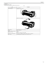
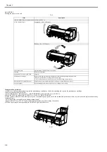
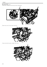
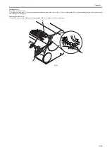
4.3.3 Units requiring draining of ink
0014-8953
iPF810 / iPF820
When disassembling the following units of the ink passage, drain the filled ink completely to prevent ink leakage. For how to drain the ink, refer to
DISASSEM-
BLY/REASSEMBLY > Points to Notes on Disassembly and Reassembly > Draining the ink.
[1] Carriage unit
Refer to DISASSEMBLY/REASSEMBLY > Points to Notes on Disassembly and Reassembly > Carriage unit.
[2] Ink tube unit
Refer to DISASSEMBLY/REASSEMBLY > Points to Notes on Disassembly and Reassembly > Ink tube unit.
[1]
Summary of Contents for iPF800 Series
Page 1: ...Aug 13 2008 Service Manual iPF800 series ...
Page 2: ......
Page 6: ......
Page 11: ...Chapter 1 PRODUCT DESCRIPTION ...
Page 12: ......
Page 14: ......
Page 38: ...Chapter 1 1 24 Hold this lever to pull out the lower roll unit ...
Page 100: ...Chapter 1 1 86 ...
Page 101: ...Chapter 2 TECHNICAL REFERENCE ...
Page 102: ......
Page 158: ......
Page 159: ...Chapter 3 INSTALLATION ...
Page 160: ......
Page 162: ......
Page 176: ...Chapter 3 3 14 ...
Page 177: ...Chapter 4 DISASSEMBLY REASSEMBLY ...
Page 178: ......
Page 180: ......
Page 238: ...Chapter 4 4 58 ...
Page 239: ...Chapter 5 MAINTENANCE ...
Page 240: ......
Page 242: ......
Page 246: ...Chapter 5 5 4 5 Close upper cover 1 F 5 6 1 ...
Page 247: ...Chapter 5 5 5 ...
Page 248: ......
Page 249: ...Chapter 6 TROUBLESHOOTING ...
Page 250: ......
Page 252: ......
Page 274: ......
Page 275: ...Chapter 7 SERVICE MODE ...
Page 276: ......
Page 278: ......
Page 301: ......
Page 302: ......
Page 303: ...Chapter 8 ERROR CODE ...
Page 304: ......
Page 306: ......
Page 318: ...Chapter 8 8 12 ...
Page 319: ...Aug 13 2008 ...
Page 320: ......


