


Chapter 2
2-8
b. TCP/IP setting of the machine is faulty
c. There is a fault in the main controller PCB, or in the installation of the PCB
d. User network is faulty
2.3.5 Checking with Loopback Address
0019-0685
imageRUNNER C1022 / imageRUNNER C1022i / Color imageRUNNER
C1030 / Color imageRUNNER C1030iF
1) Enter the loopback address (127.0.0.1) to Ping.
- In the case of 'NG', check the TCP/IP setting of the machine again, and
then execute Ping again.
- In the case of 'OK', go through the following check for local host
address.
2.3.6 Checking with Local Host Address
0019-0687
imageRUNNER C1022 / imageRUNNER C1022i / Color imageRUNNER
C1030 / Color imageRUNNER C1030iF
1) Enter the IP address of the machine to Ping.
- In the case of 'NG', check and perform the following to execute Ping
again.
a. Faulty IP address of the machine:
Check the IP address setting of the machine again/Check with the
system administrator that the allocated IP address is valid
b. Connection failure of the main controller PCB:
Check the connection of the main controller PCB connector
c. Faulty main controller PCB:
Replace the main controller PCB
- In the case of 'OK', the user's network environment can be the problem,
so inform the status to the system administrator and ask for a measure.
2.4 Checking the Images/Operations
2.4.1 Checking Image Operation
0019-0697
imageRUNNER C1022 / imageRUNNER C1022i
1) Place a test chart on the copyboard glass, make a copy from each pickup
inlet and check the followings.
- Check that there is no abnormal noise generated.
- Check the image quality in each magnification.
- Check that the number of sheet set is properly applied.
2) Specify the additional function mode items (date, time etc.) when required
by users.
3) Specify the mechanical specification settings related to users when re-
quired by users.
- Enter the Service mode.(Main Menu > 2 > 8 > Main Menu)
- COPIER > OPTION > USER
4) If changing a setting in service mode, turn OFF/ON the main power
switch.
2.5 Installing the Card Reader
2.5.1 Notice At Installation
0019-8625
imageRUNNER C1022 / imageRUNNER C1022i / Color imageRUNNER
C1030 / Color imageRUNNER C1030iF
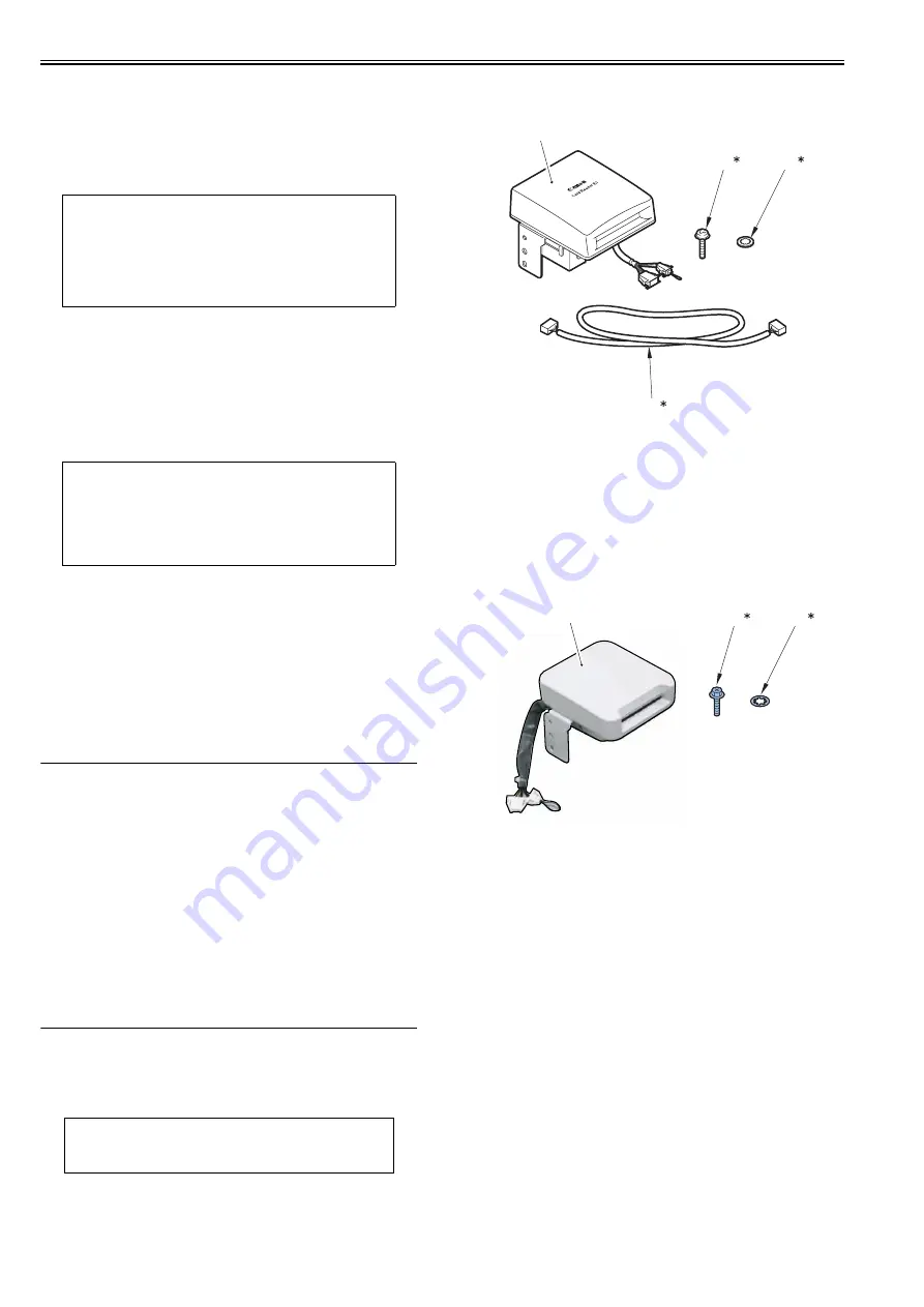
2.5.2 Checking the Contents
0019-8626
imageRUNNER C1022 / imageRUNNER C1022i / Color imageRUNNER
C1030 / Color imageRUNNER C1030iF
< Card Reader-E1 >
F-2-18
< Copy Card Reader-F1 >
F-2-19
< Card Reader Attachment Kit-F1 >
NOTE:
Because the loopback address is returned just before the main controller
PCB, you can check whether the TCP/IP setting of the machine is successful
or failed by executing Ping with this loopback address.
NOTE:
Local host address is the IP address of the machine. Thus, you can check
whether the PCB is working or faulty by executing Ping with this local host
address since the reply is returned from the main controller PCB.
CAUTION:
Installation of this equipment needs 'Card Reader Attachment Kit-F1'.
[1]
Card Reader
1pc
[2]*
Screw (TP; M3X12)
1pc
[3]*
Toothed washer
1pc
[4]*
IP-card reader cable
1pc
* Not used for this equipment.
[1]
Card Reader
1pc
[2]*
Screw (RS tight; M4X10)
1pc
[3]*
Toothed washer
1pc
* Not used for this equipment.
[2]
[3]
[4]
[1]
[2]
[3]
[1]
Summary of Contents for imageRUNNERC1022
Page 2: ......
Page 6: ......
Page 19: ...Chapter 1 Introduction ...
Page 20: ......
Page 93: ...Chapter 2 Installation ...
Page 94: ......
Page 96: ......
Page 111: ...Chapter 3 Basic Operation ...
Page 112: ......
Page 114: ......
Page 119: ...Chapter 4 Main Controller ...
Page 120: ......
Page 122: ......
Page 135: ...Chapter 5 Original Exposure System ...
Page 136: ......
Page 138: ......
Page 151: ...Chapter 6 Original Feeding System ...
Page 152: ......
Page 154: ......
Page 170: ......
Page 171: ...Chapter 7 Laser Exposure ...
Page 172: ......
Page 174: ......
Page 184: ......
Page 185: ...Chapter 8 Image Formation ...
Page 186: ......
Page 188: ......
Page 222: ......
Page 223: ...Chapter 9 Pickup and Feed System ...
Page 224: ......
Page 259: ...Chapter 10 Fixing System ...
Page 260: ......
Page 262: ......
Page 268: ...Chapter 10 10 6 ...
Page 279: ...Chapter 11 External and Controls ...
Page 280: ......
Page 311: ...Chapter 12 e Maintenance imageWARE Remote ...
Page 312: ......
Page 314: ......
Page 323: ...Chapter 12 12 9 F 12 27 ...
Page 349: ...Chapter 13 Maintenance and Inspection ...
Page 350: ......
Page 352: ......
Page 354: ......
Page 355: ...Chapter 14 Measurement and Adjustments ...
Page 356: ......
Page 358: ......
Page 361: ...Chapter 15 Correcting Faulty Images ...
Page 362: ......
Page 364: ......
Page 385: ...Chapter 16 Error Code ...
Page 386: ......
Page 388: ......
Page 399: ...Chapter 16 16 11 ...
Page 400: ......
Page 401: ...Chapter 17 Special Management Mode ...
Page 402: ......
Page 404: ......
Page 411: ...Chapter 17 17 7 ...
Page 412: ......
Page 413: ...Chapter 18 Service Mode ...
Page 414: ......
Page 492: ......
Page 493: ...Chapter 19 Upgrading ...
Page 494: ......
Page 496: ......
Page 500: ...Chapter 19 19 4 3 Click Next F 19 4 4 Select a USB connected device and click Next F 19 5 ...
Page 501: ...Chapter 19 19 5 5 Click Start F 19 6 6 Click Yes F 19 7 Download will be started F 19 8 ...
Page 504: ...Chapter 19 19 8 4 Select a USB connected device and click Next F 19 12 5 Click Start F 19 13 ...
Page 506: ...Chapter 19 19 10 ...
Page 507: ...Chapter 20 Service Tools ...
Page 508: ......
Page 510: ......
Page 514: ......
Page 515: ...Appendix ...
Page 516: ......
Page 532: ......
Page 533: ...Oct 29 2010 ...
Page 534: ......


