


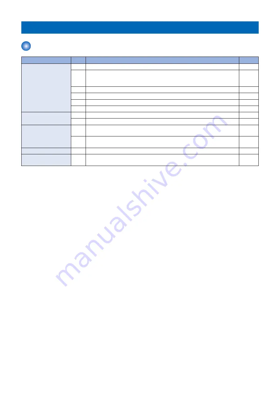
Initial Check
Initial check items list
Item
No.
Detail
Check
Site Environment
1
The voltage of the power supply is as rated (±10%).
2
The site is not a high temperature / humidity environment (near a water faucet, water
boiler, humidifi er), and it is not in a cold place. The machine is not near a source of fi
re or dust.
3
The site is not subject to ammonium gas.
4
The site is not exposed to direct rays of the sun. (Otherwise, provide curtains.)
5
The site is well ventilated, and the fl oor keeps the machine level.
6
The machine's power plug remains connected to the power outlet.
Checking the Paper
7
The paper is of a recommended type.
8
The paper is not moist. Try paper fresh out of package.
Checking the Placement of
Paper
9
Check the cassette and the manual feed tray to see if the paper is not in excess of a
specifi c level.
10
If a transparency is used, check to make sure that it is placed in the correct orientation
in the manual feed tray.
Checking the Durables
11
Check the table of durables to see if any has reached the end of its life.
Checking the Periodically
Replaced Parts
12
Check the scheduled servicing table and the periodically replaced parts table, and re-
place any part that has reached the time of replacement.
6. Troubleshooting
401
Summary of Contents for imageRUNNER ADVANCE C3320 Series
Page 1: ...Revision 7 0 imageRUNNER ADVANCE C3330 C3325 C3320 Series Service Manual ...
Page 18: ...Product Overview 1 Product Lineup 7 Features 11 Specifications 17 Parts Name 26 ...
Page 518: ...Error Jam Alarm 7 Overview 507 Error Code 511 Jam Code 617 Alarm Code 624 ...
Page 1020: ...9 Installation 1008 ...
Page 1022: ...2 Perform steps 3 to 5 in each cassette 9 Installation 1010 ...
Page 1024: ...5 6 Checking the Contents Cassette Feeding Unit 1x 3x 2x 1x 9 Installation 1012 ...
Page 1027: ...3 4 NOTE The removed cover will be used in step 6 5 2x 2x 9 Installation 1015 ...
Page 1046: ...When the Kit Is Not Used 1 2 Close the Cassette 2 When the Kit Is Used 1 9 Installation 1034 ...
Page 1068: ... Removing the Covers 1 2x 2 1x 9 Installation 1056 ...
Page 1070: ...3 1x 1x 9 Installation 1058 ...
Page 1083: ...6 7 TP M4x8 2x 2x 9 Installation 1071 ...
Page 1084: ...When Installing the USB Keyboard 1 Cap Cover Wire Saddle 9 Installation 1072 ...
Page 1129: ...9 2x 10 2x 11 9 Installation 1117 ...
Page 1135: ...Remove the covers 1 ws 2x 2 1x 9 Installation 1123 ...
Page 1140: ...2 2x 3 Connect the power plug to the outlet 4 Turn ON the power switch 9 Installation 1128 ...
Page 1176: ... A 2x Installing the Covers 1 1x 2 2x 9 Installation 1164 ...
Page 1190: ...14 Install the Cable Guide to the HDD Frame 4 Hooks 1 Boss 9 Installation 1178 ...


