


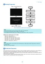


NOTE:
If the power supply is stopped without shutting down the machine, or if the processing to completely delete the hard disk (deletion
of the primary file) fails to be completed within the shutdown time (max. 90 sec.), data consistency is checked at startup, during
which the progress bar is displayed.
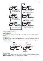
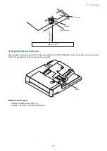
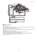
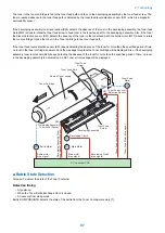
Motion Sensor
Function
Automatic recovery from sleep mode
• The machine automatically recovers from sleep mode by staying in the designated area for more than a certain period of
time. The time spent in the area varies based on the setting of sensitivity (4 levels).
• The sensor determines whether a person approaches the above mentioned area is a user. If a person approaches the
machine from the front side, it starts the operation to recover from sleep mode early. If a person approaches the machine
from the side, the sensor judges whether he/she is just a passer to prevent recovery by mistake.
CAUTION:
Recovery time depends on the time for recovery from sleep mode of the host machine. The Motion Sensor outputs the
trigger for recovery from sleep mode. Operation of the Motion Sensor is the same for recovery from Deep Sleep and from
Sleep 1, but time for recovery differs depending on the recovery process of the host machine.
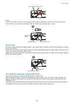
The machine is not recovered by a passer.
• Reduce unnecessary power consumption
• The machine may recover from sleep mode if walking speed is slow. However, if no operation is performed for a certain
period of time, it moves to sleep mode again.
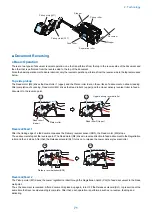
CAUTION:
Since the detection is performed by outputting a certain frequency from the output part and receiving the reflection wave
by the reception part; thus, do not block the sensor area.
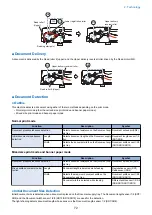
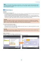
Settings / Registration
Preferences > Timer / Energy Settings > Use Motion Sensor
In Settings / Registration, you can disable the sensor and select the sensor sensitivity.
2. Technology
82
Summary of Contents for imagerunner advance 4551i
Page 19: ...Product Overview 1 Product Lineup 7 Features 13 Specifications 16 Name of Parts 26 ...
Page 155: ...Periodical Service 3 Consumable Parts List 143 Cleaning Check Adjustment Locations 146 ...
Page 392: ...Error Jam Alarm 7 Overview 380 Error Code 383 Jam Code 509 Alarm Code 520 ...
Page 545: ...Service Mode 8 Overview 533 COPIER 549 FEEDER 845 SORTER 851 BOARD 871 ...
Page 892: ...Unpacking 1 2 1200 mm 840 mm 769 mm 1230 mm 2430 mm 3 9 Installation 879 ...
Page 895: ...3 4 NOTE Keep the removed screws for relocating the host machine 2x 5 6 7 9 Installation 882 ...
Page 896: ...8 9 10 1x Installing the Air Filter 1 9 Installation 883 ...
Page 897: ...2 3 Installing the Drum Unit 1 2 3 9 Installation 884 ...
Page 899: ...8 NOTE The screw removed at procedure 4 is used 1x 9 10 11 12 9 Installation 886 ...
Page 923: ...5 6 NOTE Use the screws and Rubber Caps removed in step 1 2x 7 2x 9 Installation 910 ...
Page 935: ...7 1x 8 9 6x 10 2x 9 Installation 922 ...
Page 936: ...11 Installing the NFC Kit 1 2 2x 3 TP M3x4 1x 9 Installation 923 ...
Page 938: ...4 5 1x 6 9 Installation 925 ...
Page 985: ...8 2x 2x TP M4x8 Black When installing the USB Keyboard 1 9 Installation 972 ...
Page 991: ...7 4x 8 1x 1x Lower Cover 9 1x 10 1x 1x 9 Installation 978 ...
Page 992: ...11 1x 1x 12 1x 13 TP M3x12 2x 14 4x TP M3x6 9 Installation 979 ...
Page 997: ...Installation Procedure 1 2 2x 3 2x 4 6x 5 4x 9 Installation 984 ...
Page 998: ...6 7 NOTE Do not close the Wire Saddle 1x 1x 8 9 9 Installation 985 ...
Page 1003: ...2 1x 1x 3 2x 2x 4 9 Installation 990 ...
Page 1012: ...2 1x 1x 3 2x 2x 4 9 Installation 999 ...
Page 1014: ...7 CAUTION The connector must be contacted TP㸹M3x6 3x 1x 8 4x 9 9 Installation 1001 ...
Page 1016: ...13 4x 14 15 Binding M4x16 Binding M3x16 2x M3x16 M4x16 16 Binding M4x6 1x 9 Installation 1003 ...
Page 1023: ...Installation Procedure Preparation 1 4x 2 1x 1x 3 2x 9 Installation 1010 ...
Page 1029: ...4 5 1x 1x 9 Installation 1016 ...
Page 1048: ...3 2x TP M3x8 Black 4 2x TP M3x6 5 9 Installation 1035 ...
Page 1053: ... Installing the Removable HDD Kit 1 2x 2x 2 3 1x 4 9 Installation 1040 ...
Page 1065: ...3 2x TP M3x8 Black 4 2x TP M3x6 5 9 Installation 1052 ...
Page 1071: ... Installing the Removable HDD Kit 1 2x 2x 2 3 1x 4 9 Installation 1058 ...


