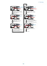


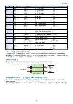


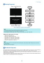
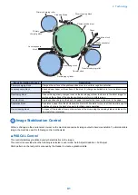


Startup Sequence
Power Supply Switch ON
Standby screen display
Power Supply
Switch ON
Initializing process of hardware
Starting BIOS
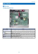
[Main Controller PCB]
Starting IPL (boot program)
and OS system software
[Flash PCB]
Starting application
[Hard disk]
Standby
screen display
Screen sequence and internal processing sequence
NOTE:
To achieve faster startup, the progress bar and the active PCB are not synchronized.
For this reason, the progress bar cannot be utilized for troubleshooting.
For information about troubleshooting, refer to "Related error codes (major error codes)" shown below.
Related error codes (major error codes):
• E602-0001: HDD detection error
• E614-0001: Flash PCB detection error
• E614-0002: Error in file system on the Flash PCB
• E614-4001: Error in file system on the Flash PCB
• E614-4002: Error in file system on the Flash PCB
• E748-2010: Flash PCB error / HDD error
NOTE:
When the following errors occur, the system of the host machine has not been started normally. Therefore the error code is not
recorded in the log.
E602-XX01, E614-XX01, E748-2010
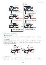
Shutdown Sequence
Before shutting down the power supply, it is necessary to perform the HDD completion process (Purpose: to prevent damage on
the HDD) and execute the fixing disengagement operation.This sequential process is called “shutdown sequence”.
With this machine, the Main Controller PCB detects turning OFF the Main Power Supply Switch, and the shutdown sequence is
started and executed automatically.
Note that the maximum shutdown time with this equipment is 90 seconds. (If the maximum of 90 seconds has elapsed, the power
supply is turned OFF by the hard timer circuit on the Relay PCB.)
2. Technology
81
Summary of Contents for imagerunner advance 4551i
Page 19: ...Product Overview 1 Product Lineup 7 Features 13 Specifications 16 Name of Parts 26 ...
Page 155: ...Periodical Service 3 Consumable Parts List 143 Cleaning Check Adjustment Locations 146 ...
Page 392: ...Error Jam Alarm 7 Overview 380 Error Code 383 Jam Code 509 Alarm Code 520 ...
Page 545: ...Service Mode 8 Overview 533 COPIER 549 FEEDER 845 SORTER 851 BOARD 871 ...
Page 892: ...Unpacking 1 2 1200 mm 840 mm 769 mm 1230 mm 2430 mm 3 9 Installation 879 ...
Page 895: ...3 4 NOTE Keep the removed screws for relocating the host machine 2x 5 6 7 9 Installation 882 ...
Page 896: ...8 9 10 1x Installing the Air Filter 1 9 Installation 883 ...
Page 897: ...2 3 Installing the Drum Unit 1 2 3 9 Installation 884 ...
Page 899: ...8 NOTE The screw removed at procedure 4 is used 1x 9 10 11 12 9 Installation 886 ...
Page 923: ...5 6 NOTE Use the screws and Rubber Caps removed in step 1 2x 7 2x 9 Installation 910 ...
Page 935: ...7 1x 8 9 6x 10 2x 9 Installation 922 ...
Page 936: ...11 Installing the NFC Kit 1 2 2x 3 TP M3x4 1x 9 Installation 923 ...
Page 938: ...4 5 1x 6 9 Installation 925 ...
Page 985: ...8 2x 2x TP M4x8 Black When installing the USB Keyboard 1 9 Installation 972 ...
Page 991: ...7 4x 8 1x 1x Lower Cover 9 1x 10 1x 1x 9 Installation 978 ...
Page 992: ...11 1x 1x 12 1x 13 TP M3x12 2x 14 4x TP M3x6 9 Installation 979 ...
Page 997: ...Installation Procedure 1 2 2x 3 2x 4 6x 5 4x 9 Installation 984 ...
Page 998: ...6 7 NOTE Do not close the Wire Saddle 1x 1x 8 9 9 Installation 985 ...
Page 1003: ...2 1x 1x 3 2x 2x 4 9 Installation 990 ...
Page 1012: ...2 1x 1x 3 2x 2x 4 9 Installation 999 ...
Page 1014: ...7 CAUTION The connector must be contacted TP㸹M3x6 3x 1x 8 4x 9 9 Installation 1001 ...
Page 1016: ...13 4x 14 15 Binding M4x16 Binding M3x16 2x M3x16 M4x16 16 Binding M4x6 1x 9 Installation 1003 ...
Page 1023: ...Installation Procedure Preparation 1 4x 2 1x 1x 3 2x 9 Installation 1010 ...
Page 1029: ...4 5 1x 1x 9 Installation 1016 ...
Page 1048: ...3 2x TP M3x8 Black 4 2x TP M3x6 5 9 Installation 1035 ...
Page 1053: ... Installing the Removable HDD Kit 1 2x 2x 2 3 1x 4 9 Installation 1040 ...
Page 1065: ...3 2x TP M3x8 Black 4 2x TP M3x6 5 9 Installation 1052 ...
Page 1071: ... Installing the Removable HDD Kit 1 2x 2x 2 3 1x 4 9 Installation 1058 ...


