


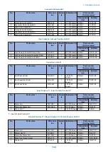


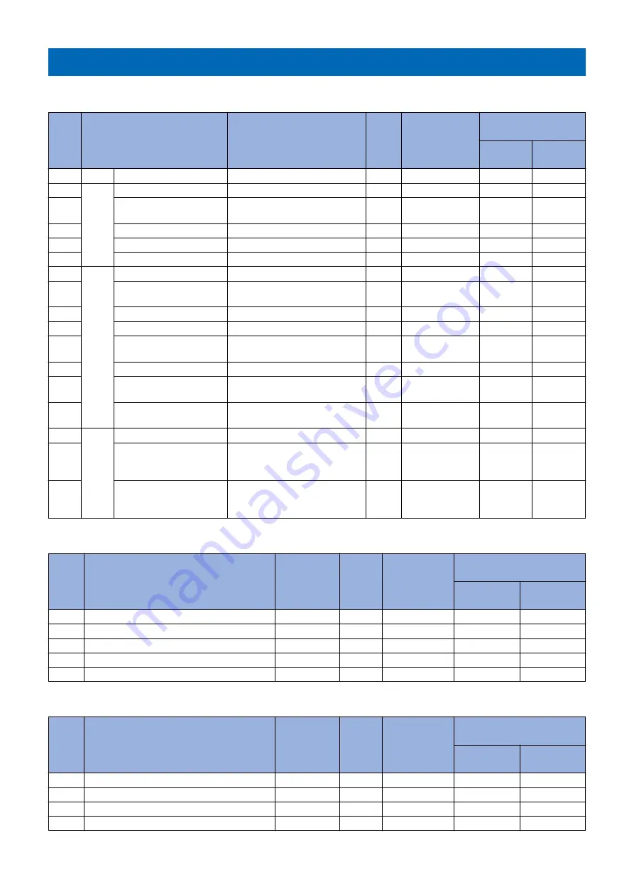
Consumable Parts List
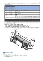
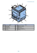
Host machine
No.
Parts name
Parts number
Quan-
tity
Estimated life
Parts counter
(Service mode)
Intermedi-
ate item
Sub item
1
Ozone Filter
FC0-3078
1
240,000 pages
DRBL-1
OZ-FIL1
2
Image
For-
mation
Sys-
tem
Transfer Roller
FE8-2935
1
300,000 pages
DRBL-1
TR-ROLL
3
Separation Static Elimina-
tor
FM3-9296
1
240,000 pages
DRBL-1
SP-SC-EL
4
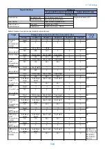
Drum Unit
-
1
-
DRBL-1
PT-DRM
5
Developing Assembly
FM1-J148
1
500,000 pages
DRBL-1
DV-UNT-K
6
Waste Toner Container
FM3-9276
1
80,000 pages
DRBL-1
WST-TNR
7
Pick-
up/
Feed
Sys-
tem
Pickup Roller (Cassette 1) FB6-3405
1
150,000 sheets
DRBL-1
C1-PU-RL
8
Separation Roller (Cas-
sette 1)
FC6-6661
1
120,000 sheets
DRBL-1
C1-SP-RL
9
Feed Roller (Cassette 1)
FC0-5080
1
150,000 sheets
DRBL-1
C1-FD-RL
10
Pickup Roller (Cassette 2) FB6-3405
1
150,000 sheets
DRBL-1
C2-PU-RL
11
Separation Roller (Cas-
sette 2)
FC6-6661
1
120,000 sheets
DRBL-1
C2-SP-RL
12
Feed Roller (Cassette 2)
FC0-5080
1
150,000 sheets
DRBL-1
C2-FD-RL
13
Multi-purpose Tray Pickup
Roller
FL3-1352
1
150,000 sheets
DRBL-1
M-FD-RL
14
Multi-purpose Tray Separa-
tion Pad
FL3-3469
1
150,000 sheets
DRBL-1
M-SP-PD
15
Fixing
Sys-
tem
Fixing Main Unit (100V)
FM1-J022
1
240,000 pages
DRBL-1
FX-UNIT
16
Fixing Main Unit (120V)
51 ppm machine: FM1-J020
25/35/45 ppm machine: FM1-
J023
1
240,000 pages
DRBL-1
FX-UNIT
17
Fixing Main Unit (230V)
51 ppm machine: FM1-J021
25/35/45 ppm machine: FM1-
J024
1
240,000 pages
DRBL-1
FX-UNIT
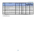
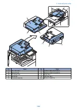
1-path ADF
No.
Parts name
Parts num-
ber
Quanti-
ty
Estimated life
Parts counter
(Service mode)
Intermediate
item
Sub item
1
Pickup Roller
FL0-3873
1
80,000 sheets
DRBL-2
DF-PU-RL
2
Feed Roller
FC0-9450
1
80,000 sheets
DRBL-2
DF-FD-RL
3
Separation Roller
FC0-9631
1
80,000 sheets
DRBL-2
DF-SP-RL
4
Pre-separation Unit
FM1-J766
1
80,000 times
DRBL-2
DF-PR-PD
5
Stamp
FC7-5465
1
7,000 times
DRBL-2
STAMP
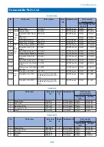
Reverse ADF
No.
Parts name
Parts num-
ber
Quanti-
ty
Estimated life
Parts counter
(Service mode)
Intermediate
item
Sub item
1
Pickup Roller
FM1-D470
1
80,000 sheets
DRBL-2
DF-PU-RL
2
Separation Roller
FM1-D471
1
80,000 sheets
DRBL-2
DF-SP-RL
3
Left Hinge
FE3-5484
1
150,000 times
DRBL-2
STAMP
4
Stamp
FB5-9410
1
7,000 times
DRBL-2
DF-HNG-L
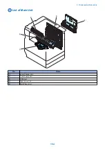
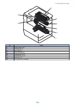
3. Periodical Service
143
Summary of Contents for imagerunner advance 4551i
Page 19: ...Product Overview 1 Product Lineup 7 Features 13 Specifications 16 Name of Parts 26 ...
Page 155: ...Periodical Service 3 Consumable Parts List 143 Cleaning Check Adjustment Locations 146 ...
Page 392: ...Error Jam Alarm 7 Overview 380 Error Code 383 Jam Code 509 Alarm Code 520 ...
Page 545: ...Service Mode 8 Overview 533 COPIER 549 FEEDER 845 SORTER 851 BOARD 871 ...
Page 892: ...Unpacking 1 2 1200 mm 840 mm 769 mm 1230 mm 2430 mm 3 9 Installation 879 ...
Page 895: ...3 4 NOTE Keep the removed screws for relocating the host machine 2x 5 6 7 9 Installation 882 ...
Page 896: ...8 9 10 1x Installing the Air Filter 1 9 Installation 883 ...
Page 897: ...2 3 Installing the Drum Unit 1 2 3 9 Installation 884 ...
Page 899: ...8 NOTE The screw removed at procedure 4 is used 1x 9 10 11 12 9 Installation 886 ...
Page 923: ...5 6 NOTE Use the screws and Rubber Caps removed in step 1 2x 7 2x 9 Installation 910 ...
Page 935: ...7 1x 8 9 6x 10 2x 9 Installation 922 ...
Page 936: ...11 Installing the NFC Kit 1 2 2x 3 TP M3x4 1x 9 Installation 923 ...
Page 938: ...4 5 1x 6 9 Installation 925 ...
Page 985: ...8 2x 2x TP M4x8 Black When installing the USB Keyboard 1 9 Installation 972 ...
Page 991: ...7 4x 8 1x 1x Lower Cover 9 1x 10 1x 1x 9 Installation 978 ...
Page 992: ...11 1x 1x 12 1x 13 TP M3x12 2x 14 4x TP M3x6 9 Installation 979 ...
Page 997: ...Installation Procedure 1 2 2x 3 2x 4 6x 5 4x 9 Installation 984 ...
Page 998: ...6 7 NOTE Do not close the Wire Saddle 1x 1x 8 9 9 Installation 985 ...
Page 1003: ...2 1x 1x 3 2x 2x 4 9 Installation 990 ...
Page 1012: ...2 1x 1x 3 2x 2x 4 9 Installation 999 ...
Page 1014: ...7 CAUTION The connector must be contacted TP㸹M3x6 3x 1x 8 4x 9 9 Installation 1001 ...
Page 1016: ...13 4x 14 15 Binding M4x16 Binding M3x16 2x M3x16 M4x16 16 Binding M4x6 1x 9 Installation 1003 ...
Page 1023: ...Installation Procedure Preparation 1 4x 2 1x 1x 3 2x 9 Installation 1010 ...
Page 1029: ...4 5 1x 1x 9 Installation 1016 ...
Page 1048: ...3 2x TP M3x8 Black 4 2x TP M3x6 5 9 Installation 1035 ...
Page 1053: ... Installing the Removable HDD Kit 1 2x 2x 2 3 1x 4 9 Installation 1040 ...
Page 1065: ...3 2x TP M3x8 Black 4 2x TP M3x6 5 9 Installation 1052 ...
Page 1071: ... Installing the Removable HDD Kit 1 2x 2x 2 3 1x 4 9 Installation 1058 ...


