4
4
4-34
4-34
Parts Replacement and Cleaning > Main Units/Parts > Removing the ADF Scan Glass > Action to Take after Replacing the ADF Scan Glass
Parts Replacement and Cleaning > Main Units/Parts > Removing the ADF Scan Glass > Action to Take after Replacing the ADF Scan Glass
glass for stream reading.)(Read both sides of the chart.)
3) Place a sheet of paper that the user usually uses on the platen glass, enter the service
mode, and then select SCAN > READER > FUNCTION > CCD > DFWLVL3.
Read the white level in the BOOK mode. (Check the transparency of the glass for BOOK
mode.)
4) Place a sheet of paper that the user usually uses on the DF, enter the service mode, and
then select SCAN > READER > FUNCTION > CCD > DF-WLVL4.
Read the white level in the DF mode (stream reading). (Check the transparency of the
glass for stream reading.)(Read both sides of the chart.)
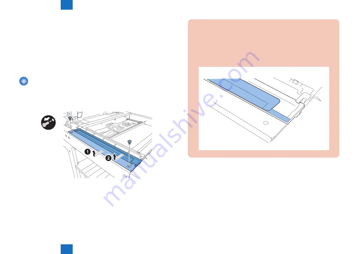
Removing the ADF Scan Glass
1) Open the platen cover (platen board cover/ADF).
2) Remove the glass retainer.
• 2 screws
3) Remove the ADF scan glass.
x2
F-4-69
CAUTION:
• When removing the ADF scan glass, take care not to touch the glass surface with
your fingers.
• Soils on the glass surface may cause white/black lines on images.
• If the glass surface is soiled, clean them with a lint-free paper moistened with
alcohol.
• Be sure to install the ADF scan glass with its seat facing front left.
F-4-70
■
Action to Take after Replacing the ADF Scan Glass
1.Enter the service mode, and then select the following:
SCAN > READER > FUNCTION > CCD > DF-WLVL1/2/3/4 (DF white level adjustment)
1) Place a sheet of paper that the user usually uses on the platen glass, enter the service
mode, and then select SCAN > READER > FUNCTION > CCD > DFWLVL1.
Read the white level in the BOOK mode. (Check the transparency of the glass for BOOK
mode.)
2) Place a sheet of paper that the user usually uses on the DF, enter the service mode, and
then select SCAN > READER > FUNCTION > CCD > DF-WLVL2.
Read the white level in the DF mode (stream reading). (Check the transparency of the
glass for stream reading.)(Read both sides of the chart.)
Summary of Contents for imageRUNNER 2545
Page 15: ...1 1 Product Overview Product Overview Product Lineup Feature Specifications Name of Parts...
Page 105: ...3 3 Periodical Service Periodical Service Consumable Parts and Cleaning Parts...
Page 177: ...5 5 Adjustment Adjustment Outline Adjustment when replacing parts Image position adjustment...
Page 195: ...7 7 Error Code Overview Error Code Jam Code Alarm Code...
Page 205: ...7 7 7 11 7 11...
Page 211: ...8 8 Service Mode Outline Details of Service Mode...
Page 354: ...Service Tools General Circuit Diagram Appendix...


