6
6-8
Basic Configuration
Functional Configuration
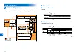
The machine may broadly be divided into the following functional system blocks; document
exposure system block, controller system block, laser exposure system block, image
formation system block, fixing system block and pickup/feed system block.
Flow of paper
Flow of signal
Laser beam
Reader relay PCB
CIS
Exposure lamp
Document exposure system
Main
controller
DC
controller
Option
board
Controller system
Duplexing
feed
Delivery
Transfer
Pickup
Fixing
Fixing
system
Image
formation
system
Pickup/feed
system
Laser exposure system
Cassette 2
Cassette 1
Laser scanner unit
F-6-5
F-6-5
Basic sequence
Sequence at Power-On
Reader
Backwarding
Main power switch
ON
SREADY
STBY
Scanner motor
LED
CIS HP sensor
Shading
position
Shading
position
Forwarding
Print sequence
Reader (Book mode, 1 original)
Backwarding
Start key
ON
SCRW
SCFW
STBY
STBY
Scanner motor
LED
CIS HP sensor
Black shading/White shading
Leading edge
of original
Shading
position
Shading
position
Trailing edge
of original
Forwarding
Backwarding
Forwarding
Light-ON
ON
ON
■
●
•
●
•
F-6-6
F-6-6
F-6-7
F-6-7
Summary of Contents for IMAGERUNNER 2530
Page 9: ...1 1 Periodical Service Consumable Parts and Cleaning Parts ...
Page 13: ...1 5 1 Cleaning Parts Fixing guide Transfer guide F 1 2 F 1 2 ...
Page 14: ...2 2 Adjustment Overview Adjustment when replacing parts image position adjustment ...
Page 20: ...3 3 Error Code Overview Error Code Jam Code Alarm Code ...
Page 34: ...4 4 Service Mode Overview Details of Service Mode ...
Page 85: ...5 5 Parts Replacement and Cleaning List of Parts ...
Page 98: ...6 6 Product Overview Specifications Product lineups Basic Configuration ...
Page 106: ...7 7 Version Upgrading Upgrading Targets and Procedure ...

