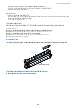

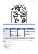


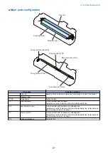


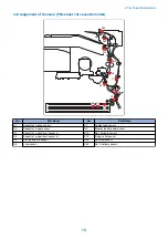
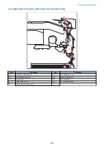


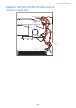
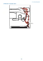

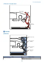


Pickup/Feed System
Overview
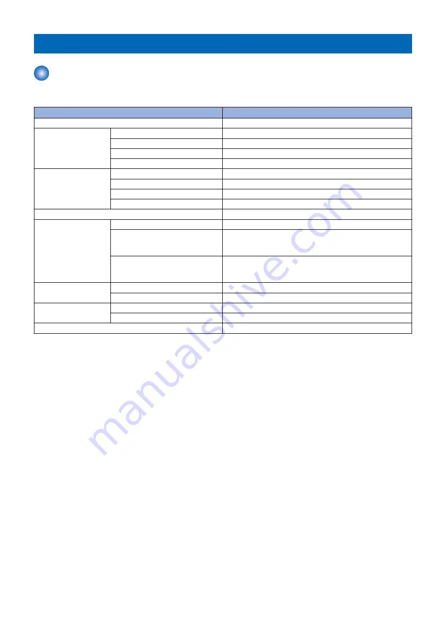
■ Specification
Item
Description
Paper storage method
Front loading method
Pickup method
Cassette 1 (550 sheets cassette)
Retard separation method
Cassette 1 (250 sheets cassette)
Pad separation method
Cassette 2/3/4
Retard separation method
Manual feed pickup tray
Pad separation method
Paper stack capacity
Cassette 1 (550 sheets cassette)
550 sheets (80 g/m2), 650 sheets (64 g/m2)
Cassette 1 (250 sheets cassette)
250 sheets (80 g/m2), 300 sheets (64 g/m2)
Cassette 2/3/4
550 sheets (80 g/m2), 650 sheets (64 g/m2)
Manual feed pickup tray
100 sheets (80 g/m2), 100 sheets (64 g/m2)
Paper feed reference
Center reference
Paper size
Cassette 1/3/4
A4, A4R, A3, A5R, B4, B5, B5R, LTR, LTTR, LG, 11" x 17", STMTR
Cassette 2
A4, A4R, A3, A5R, B4, B5, B5R, LTR, LTTR, LG, 11"" x 17"",
STMTR, Envelopes* (No.10 (COM10), ISO-B5, Monarch, ISO-C5,
DL) * The optional Envelope Feeder Attachment-D1 is required.
Manual feed pickup tray
A4, A4R, A3, A5R, B4, B5, B5R, LTR, LTTR, LG, 11" x 17", STMTR,
Free size (99 mm x 297 mm to 148 mm x 432 mm), Envelopes (No.
10 (COM10), ISO-B5, Monarch, ISO-C5, DL)
Paper grammage
Cassette
64 g/m2 to 90 g/m2
Manual feed pickup tray
64 g/m2 to 128 g/m2
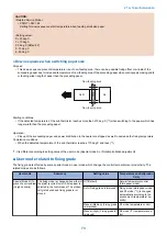
Paper size switch
Cassette
By the user
Manual feed pickup tray
By the user
Duplexing method
Through path
2. Technical Explanation
76
Summary of Contents for imageRUNNER 2525 Series
Page 1: ...Revision 9 0 imageRUNNER 2530 2525 2520 Series Service Manual ...
Page 62: ...No Part name 3 Laser unit 2 Technical Explanation 52 ...
Page 119: ...Periodical Service 3 Consumable Parts and Cleaning Parts 110 Cleaning Parts 115 ...
Page 125: ...Cleaning Parts Fixing guide Transfer guide 3 Periodical Service 115 ...
Page 136: ...List of Sensors S18 S17 S16 TS2 HU1 S9 S8 S19 TS1 S11 S12 4 Disassembly Assembly 126 ...
Page 165: ...5 Remove the idler gear 1 claw 1x 4 Disassembly Assembly 155 ...
Page 172: ... 1 4 2 3 2 2 Remove the scanner motor 4 screws 4x 4 Disassembly Assembly 162 ...
Page 186: ...3 Remove the RAM PCB Release the hook 4 Disassembly Assembly 176 ...
Page 187: ...Adjustment 5 Overview 178 Basic Adjustment 180 Adjustment when Replacing the Parts 182 ...
Page 209: ...Error Jam Alarm 7 Outline 200 Error Code 201 Jam Code 213 Alarm Code 219 ...
Page 231: ...Service Mode 8 Overview 222 Details of Service Mode 225 Remote UI Service Mode 302 ...
Page 314: ...Example of report display 8 Service Mode 304 ...
Page 387: ...APPENDICES Service Tools 378 General Circuit Diagram 379 ...