


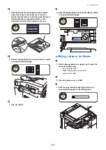
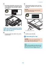

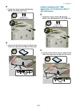


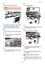


1. Insert the connector of the supplied Power cord into
the AC inlet.
2. Install the supplied power cord clamp with the
supplied screw except for India model. Insert the left
leg of the power cord clamp into the machine frame.
NOTE:
Besides Australia model, use the TP screw (M3 x 6). For
Australia model, use the stepped screw.
1x
TP
(M3x6)
Stepped Screw
(M3)
3. Plug the supplied Power cord in the wall outlet.
4. Peel off the protective seal from the operation panel.
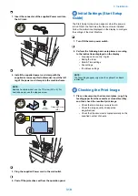
Initial Settings (Start Setup
Guide)
The Start Setup Guide screen appears when the power is
turned ON for the first time after the machine is installed.
Follow the instructions displayed on the display to configure
the settings of the Host Machine.
1. Turn ON the main power switch.
2. Perform the following basic setup items according
to the instructions displayed on the display.
• Language and country / region
• Mixing the toner
• Date & Time settings
• Fax settings
• IP address settings
NOTE:
The fax settings appear only when the optional Fax Board
is attached.
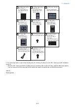
Checking the Print Image
1. Place a document on the document glass, copy it by
feeding paper from the cassette or manual-feed tray,
and then check the resultant print image.
• Check that no abnormal noise is heard.
• Check the image quality at respective
magnifications.
• Check that the document is copied normally on the
specified number of sheets.
9. Installation
319
Summary of Contents for imageRUNNER 2525 Series
Page 1: ...Revision 9 0 imageRUNNER 2530 2525 2520 Series Service Manual ...
Page 62: ...No Part name 3 Laser unit 2 Technical Explanation 52 ...
Page 119: ...Periodical Service 3 Consumable Parts and Cleaning Parts 110 Cleaning Parts 115 ...
Page 125: ...Cleaning Parts Fixing guide Transfer guide 3 Periodical Service 115 ...
Page 136: ...List of Sensors S18 S17 S16 TS2 HU1 S9 S8 S19 TS1 S11 S12 4 Disassembly Assembly 126 ...
Page 165: ...5 Remove the idler gear 1 claw 1x 4 Disassembly Assembly 155 ...
Page 172: ... 1 4 2 3 2 2 Remove the scanner motor 4 screws 4x 4 Disassembly Assembly 162 ...
Page 186: ...3 Remove the RAM PCB Release the hook 4 Disassembly Assembly 176 ...
Page 187: ...Adjustment 5 Overview 178 Basic Adjustment 180 Adjustment when Replacing the Parts 182 ...
Page 209: ...Error Jam Alarm 7 Outline 200 Error Code 201 Jam Code 213 Alarm Code 219 ...
Page 231: ...Service Mode 8 Overview 222 Details of Service Mode 225 Remote UI Service Mode 302 ...
Page 314: ...Example of report display 8 Service Mode 304 ...
Page 387: ...APPENDICES Service Tools 378 General Circuit Diagram 379 ...