


Overview
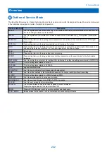
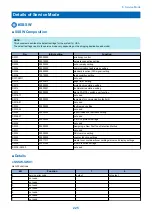
Outline of Service Mode
The items that follow may be checked/set using the machine's service mode, which is designed the way the service mode used
in fax machines is designed in terms of contents and operation.
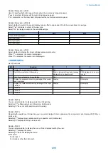
Service data item
Discription
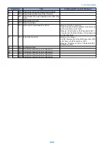
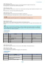
#SSSW
Use it to register/set basic fax functions (e.g., error control, echo remedy, communication error correction). Use
it to make settings related counter functions.
#MENU
Use it to register/set items related to functions needed at time of installation (e.g., NL equalizer, transmission
level).
#NUMERIC
These setting items are for inputting numeric parameters such as the various conditions for the RTN signal
transmission.
#SPECIAL
These setting items are for telephone network control functions. Do not use.
#NCU
These setting items are for telephone network control functions such as the selection signal transmission con-
ditions and the detection conditions, for the control signals sent from the exchange.
#FAX
Do not use.
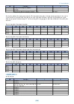
#SCAN
These setting items are for image adjustment in scanning.
These setting items are for image adjustment in printer assembly and for special mode for the field-related
measures.
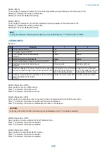
#NETWORK
Use it to confirm the contents of the installed CA certificates. Then this is a setting items related to NETWORK.
#CODEC
This is a setting items related to CODEC.
#SYSTEM
This is a setting items related to SYSTEM.
#ACC
Register the accessories.
#COUNTER
Use it to check estimates for maintenance/parts replacement.
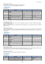
#LMS
Use it to set the inactivity of the transmitted license and the license inactivity without transmitting.
#E-RDS
This is a setting items related to e-RDS (Embedded RDS).
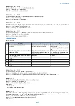
#REPORT
Use it to generate reports on various service data.
#DOWNLOAD
Use it to download firmware to the ROM of a PCB in question.
#CLEAR
Use it to reset various data to initial settings.
#DISPLAY
The error and detailed code which have happened now are displayed.
Display the engine speed of the main controller PCB.
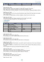
#ROM
Displays ROM information, such as version numbers and checksums.
#TEST MODE
Makes various status checks, such as contact sensor, sensor and print status.
8. Service Mode
222
Summary of Contents for imageRUNNER 2525 Series
Page 1: ...Revision 9 0 imageRUNNER 2530 2525 2520 Series Service Manual ...
Page 62: ...No Part name 3 Laser unit 2 Technical Explanation 52 ...
Page 119: ...Periodical Service 3 Consumable Parts and Cleaning Parts 110 Cleaning Parts 115 ...
Page 125: ...Cleaning Parts Fixing guide Transfer guide 3 Periodical Service 115 ...
Page 136: ...List of Sensors S18 S17 S16 TS2 HU1 S9 S8 S19 TS1 S11 S12 4 Disassembly Assembly 126 ...
Page 165: ...5 Remove the idler gear 1 claw 1x 4 Disassembly Assembly 155 ...
Page 172: ... 1 4 2 3 2 2 Remove the scanner motor 4 screws 4x 4 Disassembly Assembly 162 ...
Page 186: ...3 Remove the RAM PCB Release the hook 4 Disassembly Assembly 176 ...
Page 187: ...Adjustment 5 Overview 178 Basic Adjustment 180 Adjustment when Replacing the Parts 182 ...
Page 209: ...Error Jam Alarm 7 Outline 200 Error Code 201 Jam Code 213 Alarm Code 219 ...
Page 231: ...Service Mode 8 Overview 222 Details of Service Mode 225 Remote UI Service Mode 302 ...
Page 314: ...Example of report display 8 Service Mode 304 ...
Page 387: ...APPENDICES Service Tools 378 General Circuit Diagram 379 ...