


Embedded RDS
Product Overview
■ Overview
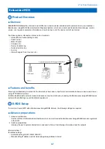
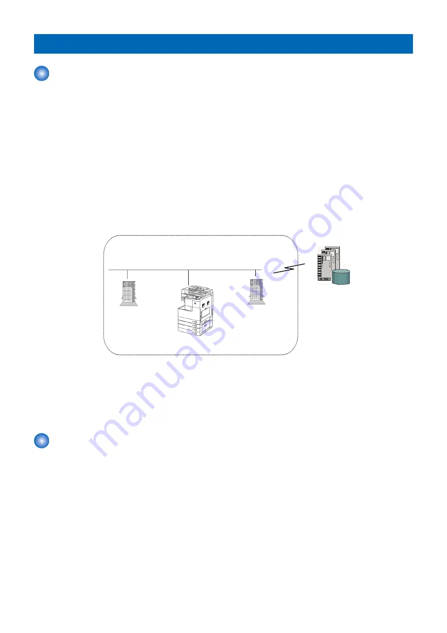
EMBEDDED RDS(hereafter, referred to as E-RDS) is a network module embedded with customer's device, and enables e-
Maintenance/ imageWARE Remote (Remote Diagnosis System), which can collects and transmits status changes, counter
values, error log and consumable information such as toner low/ out of the device to UGW via Internet.
The following device information / status can be monitored.
• Service Mode Counter (Billing counts)
• Parts Counter
• Mode Counter
• Firmware Info.
• Device Condition log
• Service Call Error log
• Jam log
• Status changes (Toner low/ out, etc.)
UGW
F
ire
w
a
ll
Communication with UGW using HTTPS/SOAP
Proxy server
Intranet
Internet
DNS server
■ Features and benefits
Since high confidentiality is required for the information shown above, it performs communication between a device and a server
using HTTPS/SOAP protocol.
E-RDS embedded with a network module in advance can realize a front-end processing of e-Maintenance/ imageWARE Remote
system without attaching any extra hardware equipment.
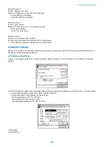
E-RDS Setup
To monitor a Copier/ MFP with e-Maintenance/ imageWARE Remote, the following settings are required.
■ Advance preparations
1. Advance confirmation
Confirm with the UGW administrator that the device to be monitored with e-Maintenance/ imageWARE Remote is registered
in the UGW.
2. Advance preparations
Interview the user's system administrator in advance to find out the following information about the network.
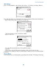
Information item 1
IP address settings
• Automatic setting (DHCP, RARP, BOOTP)
• Manual setting IP address, subnet mask and gateway address to be set
2. Technical Explanation
97
Summary of Contents for imageRUNNER 2525 Series
Page 1: ...Revision 9 0 imageRUNNER 2530 2525 2520 Series Service Manual ...
Page 62: ...No Part name 3 Laser unit 2 Technical Explanation 52 ...
Page 119: ...Periodical Service 3 Consumable Parts and Cleaning Parts 110 Cleaning Parts 115 ...
Page 125: ...Cleaning Parts Fixing guide Transfer guide 3 Periodical Service 115 ...
Page 136: ...List of Sensors S18 S17 S16 TS2 HU1 S9 S8 S19 TS1 S11 S12 4 Disassembly Assembly 126 ...
Page 165: ...5 Remove the idler gear 1 claw 1x 4 Disassembly Assembly 155 ...
Page 172: ... 1 4 2 3 2 2 Remove the scanner motor 4 screws 4x 4 Disassembly Assembly 162 ...
Page 186: ...3 Remove the RAM PCB Release the hook 4 Disassembly Assembly 176 ...
Page 187: ...Adjustment 5 Overview 178 Basic Adjustment 180 Adjustment when Replacing the Parts 182 ...
Page 209: ...Error Jam Alarm 7 Outline 200 Error Code 201 Jam Code 213 Alarm Code 219 ...
Page 231: ...Service Mode 8 Overview 222 Details of Service Mode 225 Remote UI Service Mode 302 ...
Page 314: ...Example of report display 8 Service Mode 304 ...
Page 387: ...APPENDICES Service Tools 378 General Circuit Diagram 379 ...