Chapter 1
1-44
Service work
[Reference] Explain to the customer that setting the paper upside down might improve the symptom.
1) Set Service Mode (Lv2) > Mode List > COPIER > Adjust > FEED-ADJ > PFIX-FAN to "2".
("0" by default)
The change of the value increases the wind intensity from the pre-fixing feed attraction fan
[Note] Change of this setting makes the operating noise a bit louder.
2) Output the image having shown the symptom, and check that the symptom does not occur.
1.1.3 Malfunction
1.1.3.1 No Power
1.1.3.1.1 Main power does not turn on even the main power switch is turned ON
0031-5551
[ Manual-related ]
Description
The machine cannot operate when the main power is turned ON.
Field Remedy
If the machine cannot operate when the main power is turned ON, check the breaker. If the breaker is switched to the OFF position, do not attempt to turn ON the
breaker yourself, and be sure to contact your local authorized Canon dealer.
1.1.3.1.2 No display appears on LCD due to disconnection of connectors
0031-7866
[ Verified by Canon Inc. ]
Symptom
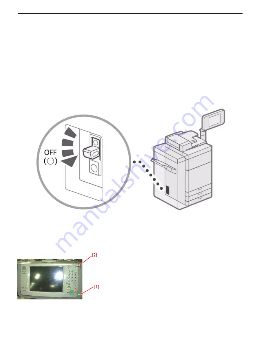
On powering-up of the main power of the main body, only the main power indicator [1] and the subpower supply lamp [2] at the control panel may be lit and the
main body may not start.
Cause
The symptom occurs when any of the following connectors at the back side of the main body is disconnected.
- J1224[1] and J1221[2] of the DC controller PCB [A]
- J1 [3] of Riser PCB [B]
- J1805 [4] of Relay PCB [C]
Summary of Contents for imagePRESS C800 Series
Page 1: ...Dec 2 2014 Troubleshooting Guide imagePRESS C800 Series...
Page 2: ......
Page 6: ......
Page 8: ......
Page 9: ...Chapter 1 Correcting Faulty Images...
Page 10: ......
Page 14: ......
Page 114: ...Chapter 1 1 100 7 2 Select the envelope type press OK...
Page 165: ...Chapter 1 1 151 3 Pull the Tray all the way out...
Page 167: ...Chapter 1 1 153 5 Remove the Waste Toner Container...
Page 172: ...Chapter 1 1 158 2 Pull out the staple cartridge holding it by the green tab...
Page 180: ...Chapter 1 1 166 5 Push in the new staple case until it clicks to insert it...
Page 181: ...Chapter 1 1 167 6 Close the Cover for the saddle stitch staple cartridge...
Page 199: ...Chapter 1 1 185 b 1 Take out the Waste Toner Container 1...
Page 201: ...Chapter 1 1 187 b 2 Install the Waste Toner Joint 1 to the Waste Toner Container 2...
Page 206: ...Chapter 1 1 192 b 9 Remove the Prism 1 1 Screw 2 1 Hook 3...
Page 207: ...Chapter 1 1 193 b 10 Clean the toner adhered to the 2 A parts on the prism...
Page 208: ...Chapter 1 1 194 b 11 Clean the toner adhered to the A part of the Waste Toner Container...
Page 210: ...Chapter 1 1 196 2 Pull out the punch waste tray...
Page 217: ...Chapter 1 1 203 3 Discard the staple waste...
Page 239: ...Chapter 1 1 225 3 Press Memory Media 4 Select the target memory media...
Page 250: ...Chapter 1 1 236 Select Share files and folders using SMB Windows Select the account to be used...
Page 255: ...Dec 2 2014...
Page 256: ......


