


Chapter 4
4-7
4.2.3 SRAM Circuit Board
0014-1298
imagePRESS C1 P / imagePRESS C1 / imagePRESS C1+ (Printer) / imagePRESS C1+
Primary control of the SRAM Circuit Board is shown below for each IC.
F-4-5
T-4-7
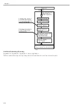
4.3 Start-Up Sequence
4.3.1 Overview
0014-1299
imagePRESS C1 P / imagePRESS C1 / imagePRESS C1+ (Printer) / imagePRESS C1+
System software used to control this unit is stored on HDD.
At startup, the CPU on the Main Controller Circuit Board loads system software from the HDD into work memory (DDR-SDRAM) on the Main Controller Circuit
Board in accordance with the BOOT ROM boot program and launches it.
The screen shown in the figure below is displayed on the Operation Panel while the CPU loads system software from the HDD and during initialization (of memory
and other system resources). Progress status is represented by a Progress Bar displayed on-screen.
F-4-6
Display of the Progress Bar indicates that the HDD is being accessed. Do not turn off power during this time, as this may lead to malfunction of the HDD (E602).
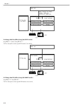
4.3.2 Startup Sequence
0014-1300
imagePRESS C1 P / imagePRESS C1 / imagePRESS C1+ (Printer) / imagePRESS C1+
IC No.
Function
IC1, 2 (SRAM)
Saves image data management information, service mode settings data, and user mode settings data saved on the HDD
IC2
IC1
BAT1
Front
Back
Progress bar
Summary of Contents for imagePRESS C1
Page 1: ...Oct 22 2008 Service Manual imagePRESS C1 Series ...
Page 2: ......
Page 6: ......
Page 38: ...Contents ...
Page 39: ...Chapter 1 Introduction ...
Page 40: ......
Page 42: ......
Page 72: ...Chapter 1 1 30 F 1 18 ...
Page 85: ...Chapter 1 1 43 T 1 26 ...
Page 88: ......
Page 89: ...Chapter 2 Installation ...
Page 90: ......
Page 94: ......
Page 234: ......
Page 235: ...Chapter 3 Basic Operation ...
Page 236: ......
Page 238: ......
Page 244: ......
Page 245: ...Chapter 4 Main Controller ...
Page 246: ......
Page 248: ......
Page 276: ...Chapter 5 Original Exposure System ...
Page 277: ......
Page 332: ...Chapter 6 Laser Exposure ...
Page 333: ......
Page 342: ...Chapter 6 6 8 F 6 10 1 Laser Light 2 Laser Shutter 3 Laser Shutter Lever 1 1 2 2 1 2 3 3 3 3 ...
Page 344: ...Chapter 7 Image Formation ...
Page 345: ......
Page 431: ...Chapter 7 7 82 ...
Page 462: ...Chapter 8 Pickup Feeding System ...
Page 463: ......
Page 504: ...Chapter 8 8 39 7 F 8 52 8 F 8 53 9 F 8 54 1 3 2 1 2 4 3 1 2 4 3 ...
Page 505: ...Chapter 8 8 40 10 F 8 55 11 F 8 56 12 F 8 57 1 4 2 3 5 4 1 3 2 1 4 2 5 3 ...
Page 506: ...Chapter 8 8 41 13 F 8 58 14 F 8 59 15 F 8 60 5 1 2 3 4 1 2 3 5 4 1 2 3 4 5 ...
Page 507: ...Chapter 8 8 42 16 F 8 61 1 2 3 4 5 ...
Page 509: ...Chapter 8 8 44 3 F 8 64 A Duplexing reversal position 4 F 8 65 2 1 A 2 1 ...
Page 510: ...Chapter 8 8 45 5 F 8 66 6 F 8 67 2 1 2 1 ...
Page 511: ...Chapter 8 8 46 7 F 8 68 8 F 8 69 3 2 1 3 2 1 ...
Page 512: ...Chapter 8 8 47 9 F 8 70 10 F 8 71 3 2 1 2 3 1 ...
Page 513: ...Chapter 8 8 48 11 F 8 72 B Duplexing re pickup stop position 12 F 8 73 3 2 B 1 3 1 2 ...
Page 514: ...Chapter 8 8 49 13 F 8 74 14 F 8 75 1 2 3 1 2 3 ...
Page 516: ...Chapter 8 8 51 F 8 77 SL3 M10 PS17 ...
Page 533: ...Chapter 8 8 68 F 8 154 1 2 4 3 2 3 4 ...
Page 534: ...Chapter 9 Fixing System ...
Page 599: ...Chapter 10 Externals and Controls ...
Page 642: ...Chapter 11 MEAP ...
Page 643: ......
Page 645: ......
Page 695: ...Chapter 12 Maintenance and Inspection ...
Page 696: ......
Page 698: ......
Page 700: ...Chapter 12 12 2 F 12 1 28 9 10 14 13 29 29 11 12 27 6 3 1 2 5 4 7 8 15 16 ...
Page 701: ...Chapter 12 12 3 F 12 2 17 20 24 23 25 26 19 18 24 21 22 ...
Page 704: ...Chapter 12 12 6 F 12 3 1 2 3 4 9 6 5 7 8 11 12 13 14 15 10 ...
Page 715: ...Chapter 12 12 17 F 12 18 1 1 2 2 ...
Page 716: ...Chapter 13 Standards and Adjustments ...
Page 717: ......
Page 719: ......
Page 732: ...Chapter 14 Correcting Faulty Images ...
Page 862: ...Chapter 15 Self Diagnosis ...
Page 894: ...Chapter 16 Service Mode ...
Page 895: ......
Page 1222: ...Chapter 17 Upgrading ...
Page 1223: ......
Page 1225: ......
Page 1256: ...Chapter 17 17 31 F 17 65 2 Turn off the main power switch and remove the USB device ...
Page 1257: ...Chapter 18 Service Tools ...
Page 1262: ......
Page 1263: ......
Page 1264: ...Oct 22 2008 ...
Page 1265: ......


