1
1
1-10
1-10
Product Overview > Service features > Use of new connectors > Features
Product Overview > Service features > Use of new connectors > Features
■
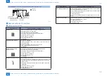
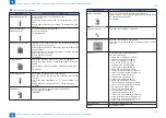
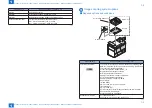
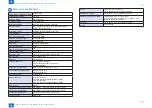
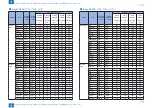
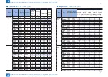
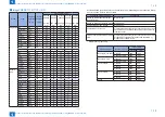
Location Code
Device
DISPLAY>JAM
DISPLAY>ERR
imagePRESS
1135 / 1135+
/1125 / 1125+
/ 1110 /1110+ -
ARCNET option
imagePRESS
1110 /1110+ -
IPCoption
imagePRESS 1135 / 1135+
/1125 / 1125+ / 1110 /1110+
00
←
Main controller = 00
Printer engine = 05
Color Image Reader-L1
(DADF)
01
←
01 or 04
POD Deck-C1/
Secondary POD Deck-C1
11
12(2nd)
13(3rd)
---
Same the JAM
Multi Drawer Document
Insertion Unit-A1
21
---
Professional Puncher-B1/
Professional Puncher
Integration Unit-A1
31
02
High Capacity Stacker-E1
51
52(2nd)
---
Perfect Binder-C1
61
---
Paper Folding Unit-F1
02
←
Finisher-AK1/
Saddle FinisherAK2
02
---
Booklet Trimmer-D1/ Two-
Knife Booklet Trimmer-A1
02
---
Document Insertion Unit-F1
71
02
Side Paper Deck-AF1
(Multi Drawer)
---
00
T-1-7
Use of new connectors
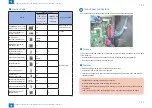
Some connectors on controller boards now use a new connector construction.
■
Purpose
The purpose of the new connector construction is to prevent communication errors as a result
of the following:
• Connectors loosening and disconnection due to vibrations during transportation.
• Poor connection of connectors during service.
■
Features
• Raised housing, making the connectors easier to pull out.
• Connectors require less force to be inserted.
• Lever lock construction. Correct insertion can be judged by an audible 'click' and physical
clicking sensation.
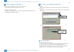
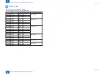
Cautions when inserting or removing connectors
Note the following points when carrying out service, etc.
Release the lock lever and then pull the housing to remove the connector. Do not pull on
the cables.
Insert the housing into the socket straight on. Do not insert the housing at an angle.
F-1-11
Summary of Contents for imagePRESS 1110
Page 242: ...3 3 Periodical Service Periodical Service Periodical service item ...
Page 655: ...5 5 Adjustment Adjustment Overview When replacing parts Major adjustment ...
Page 944: ...8 8 Service Mode Service Mode Overview COPIER FEEDER SORTER BOARD Situation Mode ...
Page 1555: ... Service Tools General Circuit Diagram General Timing Chart Operator Maintenance Appendix ...


