


I
NTRODUCTION
8
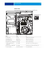
How the imagePASS operates
When a customer prints, the motherboard and copier interface board process image data.The
copier interface board is a custom board and allows the imagePASS to communicate with the
copier. The CPU, which is located on the motherboard, controls the transfer of image data to
and from the motherboard and runs the interpreter. DIMMs, which are also located on the
motherboard, hold image data during printing.
The interpreter rasterizes the page description file and compresses the image pattern into
memory using compression technology. The interpreter outputs the compressed raster data
through the image frame buffer memory to the copier interface board. The raster data is sent
to the copier, which then renders the image on paper at maximum speed.
F
IGURE
2:
Functional diagram
Motherboard
Power supply
External
devices
+3.3/+5/±12V DC
AC power
Copier
USB 2.0 (x4)
Super
I/O
Memory
CPU
Networked
computers
PCI bus
Copier interface
Lower RJ-45
Crossover
cable
Dongles/
USB flash
drives
imagePASS
DIMM 1
Unused slot
PCI-E
DIMM 2
FAN 1
PCI-E
Copier
interface
SATA 6 SATA 4 SATA 2
SATA 5 SATA 3 SATA 1
FAN 2
HDD
Network port
Upper RJ-45
Straight-through
cable
Intel 3100


