


21
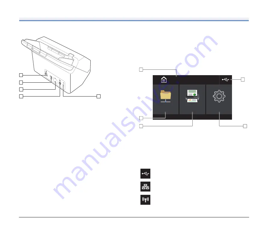
Back View
A
LAN Connector
Connect a network cable that supports RJ-45 (10Base-T/100Base-
TX/1000Base-T).
B
USB Connector
Connect the supplied USB cable to this connector.
C
Connector for Options
This can be used if you purchase options (such as an NFC reader).
Covered with a sticker at the factory. Peel off this sticker to use
options.
D
Power Connector
Connect the supplied AC adapter to this connector.
E
Theft Prevention Hole (Security Slot)
Connect an anti-theft key chain or the like.
Touch Panel
The content that appears on the touch panel varies depending on the
state of the scanner.
Refer to
“Operating the Settings Menus” (See p. 37)
for details and the
operations in the various screens.
A typical example of a screen is shown below.
Home Screen
A
Title Area
Displays the title of the operating screen.
B
Switch Connections Button
Displays the switch connections screen.
The icon that is shown here changes as shown below depending
on how the scanner and computer are connected.
\
[
Z
Y
X
When connected via USB
When connected via wired LAN
When connected via Wi-Fi
䣕䣪䣣䣴䣧䣦䢢䣈䣱䣮䣦䣧䣴
䣕䣧䣶䣶䣫䣰䣩䣵
䣅䣣䣲䣶䣷䣴䣧䣑䣰䣖䣱䣷䣥䣪
䣊䣱䣯䣧
X
Y
\
[
Z
Summary of Contents for imageFORMULA DR-S150
Page 108: ...108 Dimensions 242 mm 9 5 291 mm 11 5 600 mm 23 7 378 mm 14 9 ...
Page 110: ......
Page 111: ......


