Chapter 4
4-1
4.1 Basic Construction
4.1.1 Overview
0019-8961
imageCLASS MF9170c / imageCLASS MF9150c / imageCLASS MF8450c
T-4-1
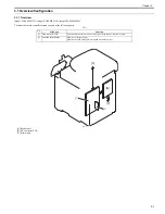
4.1.2 Major Components
0019-8963
imageCLASS MF9170c / imageCLASS MF9150c / imageCLASS MF8450c
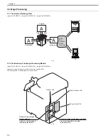
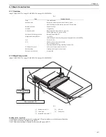
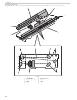
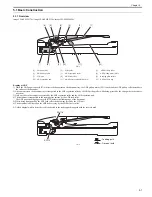
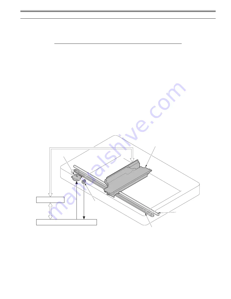
F-4-1
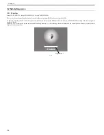
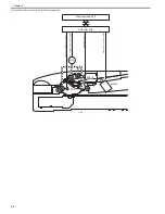
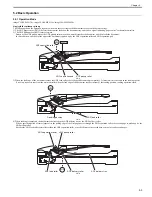
Reading on the copyboard
The document loaded on the copyboard is read by the CCD unit, which moves in the horizontal direction.
The CCD unit is driven by the reader motor (M12).
The CCD unit home position is detected by the reader HP sensor (SR717).
Item
Function/Method
Lamp
Cold-cathode tube
Document scan
Book mode: Scanning by movement of the CCD unit
ADF: Scanning in stream reading mode with CCD unit fixed
Reading resolution
600 dpi x 600 dpi
Gradation
256 gradation
Productivity (ADF)
Single-sided: 20.8 ipm (LTR), 19.7 ipm (A4)
Double-sided: Approx. 7 ipm (A4/LTR)
Detection of the carriage position
Reader HP sensor (SR717)
Magnification change (Zoom)
50 to 200 %
(Sub scanning direction only. Image processing by the main controller PCB)
Lens
Fixed focus lens
CCD
Number of lines: 1 line each for RGB
Pixels: 5400 pixels/color
Maximum document reading width: Equivalent to LTR
CCD unit drive control
Drive control by the reader motor (M12)
Document lamp
Lighting control by the inverter circuit
Document size detection
Not provided
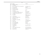
[1]
Reader motor (M12)
[2]
CCD unit
[3]
Guide shaft
[4]
Carriage belt
[5]
Reader HP sensor (SR717)
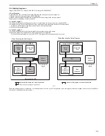
[1]
[3]
[4]
[2]
[5]
Main controller PCB
CCD relay PCB
Reader motor control signal
Reader HP signal
Summary of Contents for imageCLASS MF8450c
Page 16: ...Chapter 1 Introduction ...
Page 55: ...Chapter 2 Basic Operation ...
Page 61: ...Chapter 3 Main Controller ...
Page 75: ...Chapter 4 Original Exposure System ...
Page 88: ...Chapter 5 Original Feeding System ...
Page 105: ...Chapter 6 Laser Exposure ...
Page 113: ...Chapter 7 Image Formation ...
Page 150: ...Chapter 8 Pickup and Feed System ...
Page 184: ...Chapter 9 Fixing System ...
Page 200: ...Chapter 10 External and Controls ...
Page 230: ...Chapter 11 Maintenance and Inspection ...
Page 233: ...Chapter 12 Measurement and Adjustments ...
Page 237: ...Chapter 13 Correcting Faulty Images ...
Page 260: ...Chapter 14 Error Code ...
Page 272: ...Chapter 15 Special Management Mode ...
Page 280: ...Chapter 16 Service Mode ...
Page 322: ...Chapter 17 Upgrading ...
Page 327: ...Chapter 17 17 4 3 Click Next F 17 4 4 Select a USB connected device and click Next F 17 5 ...
Page 328: ...Chapter 17 17 5 5 Click Start F 17 6 6 Click Yes F 17 7 Download will be started F 17 8 ...
Page 330: ...Chapter 18 Service Tools ...
Page 334: ...Appendix ...
Page 349: ......

