Chapter 16
16-37
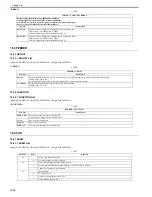
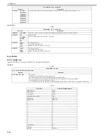
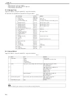
16.5.4 FAX
16.5.4.1 FAX List
0020-2027
imageCLASS MF9170c / imageCLASS MF9150c / imageCLASS MF8450c
<MODEM>
T-16-67
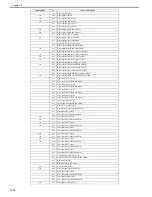
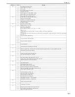
DENS-C
Not used
DENS-Y
Not used
DENS-K
Not used
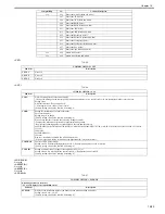
COLOR-M
Selection for each color is available
The selected color (ON) is to be output.
Setting value: 1: ON, 0: OFF
COLOR-Y
Selection for each color is available
The selected color (ON) is to be output.
Setting value: 1: ON, 0: OFF
COLOR-C
Selection for each color is available
The selected color (ON) is to be output.
Setting value: 1: ON, 0: OFF
COLOR-K
Selection for each color is available
The selected color (ON) is to be output.
Setting value: 1: ON, 0: OFF
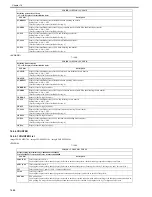
SIZE
Display paper size
PAPER
Display presence/absence of paper
MATERIAL
Display paper type
FACE UP
DOWN
Not used
FEED
Selection for the pickup position
START
Start PG pattern print
Execute output that has been selected above by pressing it.
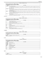
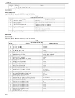
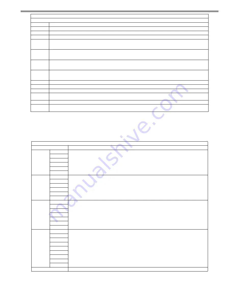
TESTMODE > FAX > MODEM
Sub item
Description
RELAY-1
CML
Test ON/OFF state of NCU's each relay and port SW
P
S
H
D
R
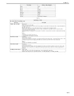
RELAY-2
CI2
Test ON/OFF state of NCU's each relay and port SW
C1
NOR
DCSEL
DCLIN
IPSEL1
FREQ
462Hz
Close DC circuit to deliver the selected frequency using the modem's tone delivery function.
1100Hz
1300Hz
1500Hz
1650Hz
1850Hz
2100Hz
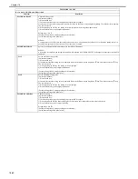
G3TX
300bps
Close DC circuit to deliver the selected signal pattern with the selected frequency using the modem's G3 signal delivery function.
2400bps
4800bps
7200bps
9800bps
TC7200
TC9600
12000bp
14400bp
DTMFTX (LONG)
Close DC circuit to deliver DTMF signal using the modem's DTMF delivery function.
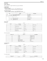
TESTMODE > PRINT
Printing PG pattern
Sub item
Description
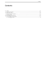
Summary of Contents for imageCLASS MF8450c
Page 16: ...Chapter 1 Introduction ...
Page 55: ...Chapter 2 Basic Operation ...
Page 61: ...Chapter 3 Main Controller ...
Page 75: ...Chapter 4 Original Exposure System ...
Page 88: ...Chapter 5 Original Feeding System ...
Page 105: ...Chapter 6 Laser Exposure ...
Page 113: ...Chapter 7 Image Formation ...
Page 150: ...Chapter 8 Pickup and Feed System ...
Page 184: ...Chapter 9 Fixing System ...
Page 200: ...Chapter 10 External and Controls ...
Page 230: ...Chapter 11 Maintenance and Inspection ...
Page 233: ...Chapter 12 Measurement and Adjustments ...
Page 237: ...Chapter 13 Correcting Faulty Images ...
Page 260: ...Chapter 14 Error Code ...
Page 272: ...Chapter 15 Special Management Mode ...
Page 280: ...Chapter 16 Service Mode ...
Page 322: ...Chapter 17 Upgrading ...
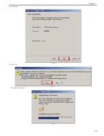
Page 327: ...Chapter 17 17 4 3 Click Next F 17 4 4 Select a USB connected device and click Next F 17 5 ...
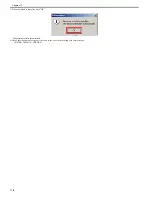
Page 328: ...Chapter 17 17 5 5 Click Start F 17 6 6 Click Yes F 17 7 Download will be started F 17 8 ...
Page 330: ...Chapter 18 Service Tools ...
Page 334: ...Appendix ...
Page 349: ......


