Chapter 10
10-4
10.2 Control Panel
10.2.1 Overview
0020-9234
imageCLASS MF9170c / imageCLASS MF9150c / imageCLASS MF8450c
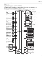
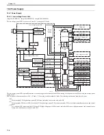
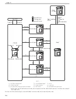
Control panel on the host machine consists of the following PCBs and LCD.
Following is the main function of the control panel.
- LCD display
- Turning ON the control panel LED
- Entry with hard keys, wheel and volume
- Interface control for the USB memory, CF card and SD/MS card
F-10-2
CPU on the main controller PCB transmits the data (display information) to the control panel main PCB according to the programs.
The data is transmitted to color LCD via control panel main PCB.
Color LCD
Control panel
Control panel
jog PCB
Control panel main PCB
J201B
J102A
J103A
J8114
J8103
J202A
J205A
J201A
J204A
J105A
Panel relay PCB
Main controller PCB
Summary of Contents for imageCLASS MF8450c
Page 16: ...Chapter 1 Introduction ...
Page 55: ...Chapter 2 Basic Operation ...
Page 61: ...Chapter 3 Main Controller ...
Page 75: ...Chapter 4 Original Exposure System ...
Page 88: ...Chapter 5 Original Feeding System ...
Page 105: ...Chapter 6 Laser Exposure ...
Page 113: ...Chapter 7 Image Formation ...
Page 150: ...Chapter 8 Pickup and Feed System ...
Page 184: ...Chapter 9 Fixing System ...
Page 200: ...Chapter 10 External and Controls ...
Page 230: ...Chapter 11 Maintenance and Inspection ...
Page 233: ...Chapter 12 Measurement and Adjustments ...
Page 237: ...Chapter 13 Correcting Faulty Images ...
Page 260: ...Chapter 14 Error Code ...
Page 272: ...Chapter 15 Special Management Mode ...
Page 280: ...Chapter 16 Service Mode ...
Page 322: ...Chapter 17 Upgrading ...
Page 327: ...Chapter 17 17 4 3 Click Next F 17 4 4 Select a USB connected device and click Next F 17 5 ...
Page 328: ...Chapter 17 17 5 5 Click Start F 17 6 6 Click Yes F 17 7 Download will be started F 17 8 ...
Page 330: ...Chapter 18 Service Tools ...
Page 334: ...Appendix ...
Page 349: ......

