


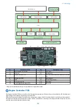


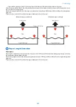


Image Formation Process
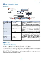
■ Overview
Pickup
6. Separation
7. Fixing
Delivery
3. Laser-beam exposure
4. Developing
1. Pre-exposure
: Paper path
: Direction of the drum
rotation
: Functional block
: Step
5. Transfer
Fixing
Transfer
Latent image formation
Developing
2. Primary charging
8. Drum cleaning
Cleaning
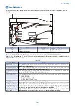
Block
No.
Process
Description
Static latent image formation
block
1
Pre-exposure
Residual charge on the Photosensitive Drum is removed using Pre-
Exposure Led Unit.
2
Primary charging
The surface of the Photosensitive Drum is uniformly charged with
negative potential.
3
Laser beam exposure
Static latent images are formed on the photosensitive drum with
laser beam irradiation. (Image exposure: Area exposed by laser is
the image area)
Developing block
4
Development
Negatively charged toner on the Developing Roller is transferred
and attached onto the Photosensitive Drum with contact develop-
ment method.
Transfer block
5
Transfer
Toner on the surface of the Photosensitive Drum is transferred to a
paper by applying positive charge to the Transfer Roller.
6
Separation
With the curvature separation method, the paper is separated from
the Photosensitive Drum. In the case of thin paper which has low
elastic force, the Static Eliminator reduces the electric charge on
the back side of paper to make the thin paper to be separated easily.
Fixing block
7
Fixing
Toner on the paper is fixed on the paper using heat and pressure.
Cleaning block
8
Drum cleaning
Residual toner on the Primary Transfer Roller and Transfer Roller
is transferred to the Photosensitive Drum, and the Developing Roll-
er collects the residual roller on the Photosensitive Drum into the
Developer.
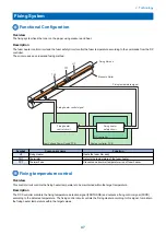
Cartridge
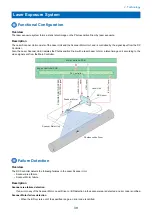
■ Functional Configuration
The cartridges have the function to form a visible image on the Photosensitive Drum with toner.
The cartridge on this machine is Drum separated type Cartridge. The Toner Cartridge and the Drum Cartridge are combined to
operate as one such as conventional integral type cartridge structures.
The Toner Cartridge is composed of the Toner and the Developer and the Drum Cartridge is composed of the Photosensitive
Drum and the Primary Charging Roller.
The DC Controller drives the Main Motor (M2) to rotate the Photosensitive Drum and the Developing Roller The Primary Charging
Roller rotates by following the Photosensitive Drum rotation.
2. Technology
42
Summary of Contents for imageCLASS MF264dw
Page 13: ...Product Overview 1 Product Lineup 6 Features 8 Specifications 9 Parts Name 14 ...
Page 67: ...Consumable Parts Consumable parts are not required in this machine 3 Periodical Service 59 ...
Page 68: ...Periodical Service No periodic services are required to this machine 3 Periodical Service 60 ...
Page 89: ...3 80 mm 80 mm 4 Parts Replacement and Cleaning 81 ...
Page 92: ... If the Fax is not installed 3x 2x 1x 2 60 mm 3 4 Parts Replacement and Cleaning 84 ...
Page 96: ...3 4 Parts Replacement and Cleaning 88 ...
Page 97: ...4 5 4 Parts Replacement and Cleaning 89 ...
Page 105: ...2 3 1x 4 Parts Replacement and Cleaning 97 ...
Page 110: ...5 6 4x 1x 1x 7 4 Parts Replacement and Cleaning 102 ...
Page 115: ...3 4 5 4 Parts Replacement and Cleaning 107 ...
Page 116: ...6 4 Parts Replacement and Cleaning 108 ...
Page 122: ...2 3 4 4 Parts Replacement and Cleaning 114 ...
Page 124: ...1 2 2x 3 4 4 Parts Replacement and Cleaning 116 ...
Page 127: ...2 3 4 2x 1x 5 4 Parts Replacement and Cleaning 119 ...
Page 129: ...3 4 2x 1x 5 6 4 Parts Replacement and Cleaning 121 ...
Page 132: ...5 2x 4 Parts Replacement and Cleaning 124 ...
Page 138: ...2 1x 3 1x 4 4 Parts Replacement and Cleaning 130 ...
Page 140: ... Procedure 1 2 4 Parts Replacement and Cleaning 132 ...
Page 144: ... Procedure 1 2 3 2x 4 Parts Replacement and Cleaning 136 ...
Page 146: ...3 4 4 Parts Replacement and Cleaning 138 ...
Page 147: ...5 4 Parts Replacement and Cleaning 139 ...
Page 153: ...1 2 3 4 4 Parts Replacement and Cleaning 145 ...
Page 155: ...1 2 2x 3 4 4 Parts Replacement and Cleaning 147 ...
Page 158: ...2 3 4 2x 1x 5 4 Parts Replacement and Cleaning 150 ...
Page 160: ...3 4 2x 1x 5 6 4 Parts Replacement and Cleaning 152 ...
Page 163: ...5 2x 4 Parts Replacement and Cleaning 155 ...
Page 166: ...2 2x 1x 1x 3 1x 1x 4 Parts Replacement and Cleaning 158 ...
Page 170: ...2 2x 3 4 2x 4 Parts Replacement and Cleaning 162 ...
Page 173: ...2 3 4 2x 1x 5 4 Parts Replacement and Cleaning 165 ...
Page 175: ...3 4 2x 1x 5 6 4 Parts Replacement and Cleaning 167 ...
Page 178: ...5 2x 4 Parts Replacement and Cleaning 170 ...
Page 183: ...2 4x 4 Parts Replacement and Cleaning 175 ...
Page 188: ... If the Fax is not installed 6 2x 1x 7 3x 8 2x 1x 4 Parts Replacement and Cleaning 180 ...
Page 191: ...4 1x 5 1x 6 3x 4 Parts Replacement and Cleaning 183 ...
Page 199: ... Procedure 1 3x 2x 4 Parts Replacement and Cleaning 191 ...
Page 201: ... If the Fax is not installed 2 4x 3 4 Parts Replacement and Cleaning 193 ...
Page 208: ...4 4 Parts Replacement and Cleaning 200 ...
Page 211: ...3 2x 4 1x 4 Parts Replacement and Cleaning 203 ...
Page 213: ...2 3 4x 4 4 Parts Replacement and Cleaning 205 ...
Page 217: ...3 1x 1x 4 5 2x 6 4 Parts Replacement and Cleaning 209 ...
Page 218: ...7 8 9 4 Parts Replacement and Cleaning 210 ...
Page 223: ...4 4 Parts Replacement and Cleaning 215 ...
Page 228: ...Adjustment 5 Adjustment at Parts Replacement 221 ...
Page 230: ...Troubleshooting 6 Test Print 223 Troubleshooting Items 226 Debug Log 228 Version Upgrade 231 ...
Page 242: ...Error Jam Alarm 7 Overview 235 Error Code 238 Jam Code 241 Alarm Code 243 ...
Page 251: ...Alarm Code This machine does not have any Alarm Code 7 Error Jam Alarm 243 ...
Page 287: ...APPENDICES Service Tools 280 General Circuit Diagram 281 Backup Data 283 ...


