Chapter 5
5-1
5.1 Periodic Replacement Parts
5.1.1 Periodic Replacement Parts
0012-6595
5.2 Consumable Parts
5.2.1 Consumable Parts
0031-2598
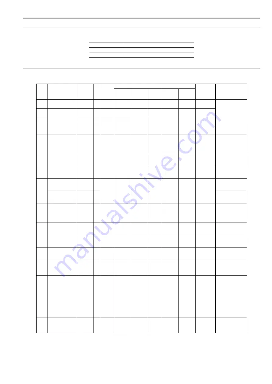
*1: The counter name is the name of "SERVICE MODE > COUNTER > PARTS CNT. > COUNTER XX-X".
*2: The exchange timing varies by the print mode and operating condition and others. (Print condition: coated paper/ print mode of photo and illustration/
each color 12.5% duty X 4(total 50% duty))
*3: When displaying the message of "W: Level1" or "W: Level2", the printer continues to operate. And when displaying the error code, the printer stops
to operate.
*4: The operation panel do not display the message, but the condition is printed in the "PRINT INF".
Level
Periodic Replacement Part
User
None
Service Personnel
None
Count
er
name
*1
Name
Parts
number
Q't
y
Life
sheets/
A0 *2
Warning level thresholds
Panel message *3
Count
contents
Reference page of
"Points to Note on
Disassembly and
Reassembly"
Level1
Level2
Unit
Level1
Level2
CR1
CARRIAGE UNIT
QM4-8458 1
14000
11228571
12476190
(X210)
mm
W: Level1 W: Level2 Carriage scan
distances
"Carriage Unit" >
"Removing the
Carriage Unit"
CR2
FLEXIBLE CABLE
UNIT
QM3-4613 1
38100
6030000
6700000
times
W: Level1 W: Level2 Carriage scan
times
CR3
CARRIAGE UNIT
QM4-8458 1
14900
14850000
16500000
(X1,000,
000) dots
W: Level1 W: Level2 Total ink
discharge
quantity
SCALE, LINEAR
QD1-0006 1
"Linear Encoder" >
"Removing the Linear
Encoder"
CR4
CARRIAGE UNIT
QM4-8458 1
50000
54000
60000
times
W: Level1 W: Level2 Number of
carriage
height
changing cam
rotation
Carriage Unit >
"Removing the
Carriage Unit"
CR5
MULTI SENSOR
UNIT
QM3-5831 1
14900
14850000
16500000
(X100)
dots
W: Level1 W: Level2 Total ink
discharge
quantity
"Multi Sensor" >
"Removing the Multi
Sensor"
SP1
INK TUBE UNIT
QM3-5951 1
25000
3960000
4400000
W: Level1 W: Level2 Carriage scan
times
"Ink Tube Unit" >
"Removing the Ink
Tube Unit"
PG1
PURGE UNIT
QM3-5988 1
50000
45000
50000
times
W: Level1 W: Level2 Number of
suction pump
rotation
"Purge Unit" >
"Removing the Purge
Unit"
JOINT, TUBE,
COLOR
QC3-1437 1
"Purge Unit" >
"Removing the Waste
Ink Tube Joint (CL)"
Hma1 HEAD
MANAGEMENT
SENSOR UNIT
QM3-5956 1
100700
30.35
31.29
ml
W: Level1 W: Level2 Ink discharge
quantity to
head
management
sensor
"Head Management
Sensor" > "Removing
the Head Management
Sensor"
MT1
MOTOR, DC
QK1-5068 1
340900
13500
15000
hours
- *4
- *4
Carriage scan
hours
"Drive Unit" >
"Removing the
Carriage Motor"
PL1
MOTOR, DC
QK1-5067 1
31800
700.20
778
hours
- *4
- *4
Paper feed
hours
"Drive Unit" >
"Removing the Feed
Motor"
Mi1
MIST FAN DUCT
UNIT
QM3-5853 1
15208
34.97
38.85
ml
W: Level1 E144-4001 Mist
collection
quantity
"Waste Ink Collection
Unit" > "Removing the
Mist Exhaust Duct"
CT1
CUTTER
QM3-5846 1
100000
90000
100000
times
W: Level1 W: Level2 Cut times (cut
operation to
the forward
direction)
"Cutter" > "Removing
the Cutter"
WF1
M/C HOLDER
UNIT
QM3-5841 1
-
254.21
282.45
ml
W: Level1 E144-4001 Waste ink
quantity by
suction
operation that
has been
executed
during
detachment of
the
maintenance
cartridge
"Purge Unit" >
"Removing the Waste
Ink Tube Joint (CL)"
WF2
WASTE INK BOX
UNIT
QM3-5805 1
37282
42.53
47.25
ml
W: Level1 E144-4001 Mist
collection
quantity by
platen fan
"Waste Ink Collection
Unit" > "Removing the
Platen Exhaust Duct"
Summary of Contents for image Prograf iPF780 Series
Page 1: ...Mar 27 2014 Service Manual iPF780 760 750 series iPF785...
Page 9: ...Chapter 1 PRODUCT DESCRIPTION...
Page 57: ...Chapter 2 TECHNICAL REFERENCE...
Page 117: ...Chapter 3 INSTALLATION...
Page 125: ...Chapter 4 DISASSEMBLY REASSEMBLY...
Page 175: ...Chapter 4 4 49 2 Shaft Cleaner 1 F 4 97 1 1...
Page 176: ...Chapter 4 4 50 3 Upper Cover Hinge Catch 1 Roll Cover Slide Guide 2 F 4 98 2 1...
Page 179: ...Chapter 5 MAINTENANCE...
Page 186: ...Chapter 6 TROUBLESHOOTING...
Page 212: ...Chapter 7 SERVICE MODE...
Page 267: ...Mar 19 2014 PARTS CATALOG iPF786 785 781 780 765 760 755 750...
Page 301: ...2 25 FIGURE 10 PLATEN GUIDE UNIT 1 3 6 2 8 4 5 10 10 10 9 9 11...
Page 326: ......


