Chapter 4
4-44
4.3.13 Head Management Sensor
0023-3339
a) Head Management Sensor
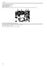
Removing the Head Management Sensor
1) Remove the purge unit.
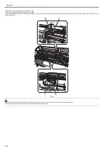
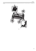
2) Remove one screw [1] and one disconnect connector [2], release one protrusion [3], and then remove the head management sensor [4].
F-4-94
b) Procedure after replacing the head management sensor
Since the distance between the head management sensor and the carriage unit varies among printers, the optical axis is factory-adjusted to adjust the non-discharging
detection position. When you have replaced the head management sensor or performed assembly/reassembly of surrounding parts that can change the distance be-
tween the head management sensor and the carriage unit, reasjustment is required.
Peform the readjustment in the service mode.
Service mode : SERVICE MODE > ADJUST > NOZZLE CHK POS.
[1]
[4]
[2]
[3]
Summary of Contents for image Prograf iPF780 Series
Page 1: ...Mar 27 2014 Service Manual iPF780 760 750 series iPF785...
Page 9: ...Chapter 1 PRODUCT DESCRIPTION...
Page 57: ...Chapter 2 TECHNICAL REFERENCE...
Page 117: ...Chapter 3 INSTALLATION...
Page 125: ...Chapter 4 DISASSEMBLY REASSEMBLY...
Page 175: ...Chapter 4 4 49 2 Shaft Cleaner 1 F 4 97 1 1...
Page 176: ...Chapter 4 4 50 3 Upper Cover Hinge Catch 1 Roll Cover Slide Guide 2 F 4 98 2 1...
Page 179: ...Chapter 5 MAINTENANCE...
Page 186: ...Chapter 6 TROUBLESHOOTING...
Page 212: ...Chapter 7 SERVICE MODE...
Page 267: ...Mar 19 2014 PARTS CATALOG iPF786 785 781 780 765 760 755 750...
Page 301: ...2 25 FIGURE 10 PLATEN GUIDE UNIT 1 3 6 2 8 4 5 10 10 10 9 9 11...
Page 326: ......


