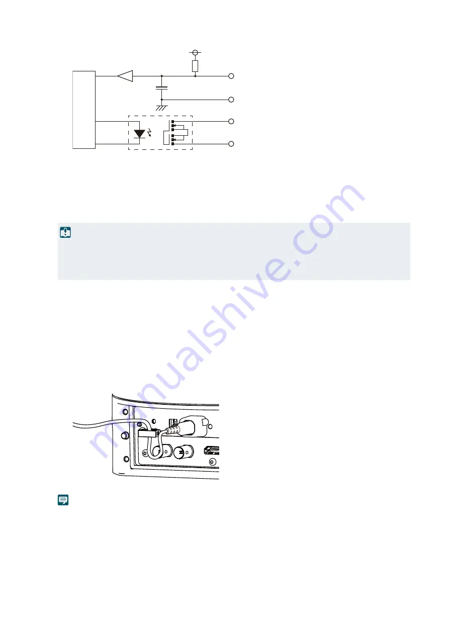
15
Internal connection diagram
(7)
LAN terminal
Terminal (RJ-45 connector) for network connections.
With PoE++ (Power over E+) capability, it is possible to provide power to the camera from the PoE++
supported hub which compile IEEE802.3bt Type 2 through a LAN cable.
Use an STP (shielded) type LAN cable with a length of 100 m or less and with a category 5e or more. Use a
category 5 or less cable may reduce the power supply capacity.
(8)
HDMI OUT terminal
Terminal for HDMI output. Take necessary measures to prevent the cable from coming off, such as using a
commercially available cable retaining part.
(9)
6G-
S
DI terminal
Output terminal (BNC connector) for uncompressed digital video and digital audio.
(10)
S
YNC terminal
Input terminal (BNC connector) for the external synchronization signal.
(11) Cable clamp
A cable clamp to prevent the power cable from coming off. Thread the cable to prevent it from coming off.
Note
• The camera does not have a power switch. Turn on/off the power by connecting/disconnecting the power cable or LAN cable or
using the switch of the device that supplies power.
• If power is supplied from both DC power and PoE++, power from DC power has a priority. If the power supply is stopped from DC
power while power is supplied from both DC power and PoE++, power supply to the camera will be stopped. In this case,
disconnect the LAN cable to stop power supply from PoE++, reconnect the cable and restart, and power will be supplied again.
Important
• Some PoE++ supported hubs can limit power usage on each port, however doing so may cause failure to operate correctly. In
this case, do not limit power usage on any port.
• Other PoE++ supported hubs can limit the total power consumption of each port, however using multiple ports doing so may fail
to operate correctly. Refer to the instruction manual of the PoE++ supported hub for use.
+3.3 V
10 kΩ
AUX IN (No.6)
AUX OUT (No.4)
GND (No.5)
AUX OUT (No.3)
0.1 μF
Input terminal
Output terminal
Internal controller


