3 System Connections
Connecting the Cables
37
2.
Place the ferrite core about 3 cm (1.2 in.) from the LAN
cable’s connector. Loop the cable once and close the ferrite
core.
Connecting the Power Supply and Network
1.
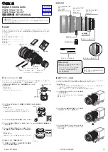
Connect the 3-pin XLR connector of a commercially available AC adapter to the DC IN 24V terminal
on the camera head (9).
If using the robotic camera system outdoors, make sure to use a power connector certified for outdoor use and
make sure the power cable is plugged all the way in.
2.
Connect the LAN cable’s connector with the ferrite core to the camera head’s LAN (Ethernet) terminal,
and the other end of the LAN cable to an Ethernet hub (10).
3.
Connect the control PC and, if necessary, the FTP server to the Ethernet hub.
Make sure to turn off the camera head before connecting/disconnecting a power source from the DC IN
24V terminal.
When using a PoE-compatible Ethernet hub, connect the LAN (Ethernet) terminal to a port without power
supply.
You can connect the control PC directly to the camera head’s LAN (Ethernet) terminal, without using an
Ethernet hub. In such case, the control PC must be used also as the FTP server if you want to use the FTP
transfer function.
Turning the System On/Off
Set the camera head’s power switch to the top position to turn on the camera head. The STATUS indicator will illuminate
in green. Set the power switch to the bottom position to turn off the camera head. The STATUS indicator will turn off.
Do not turn manually any rotating parts, as this will damage these parts. Always use the compatible
application or control device to operate the rotating parts.
Before turning on the camera head, make sure the lens’s zoom is set to the wide-angle end.
Immediately after turning on the camera head and just before turning it off, make sure to perform the
homing procedure with the web setup tool. If the homing procedure is not performed, abnormal noises
may be produced near the motion range ends. Repeatedly skipping the homing procedure may cause
malfunctions.


