Chapter 19
19-128
19.7 COUNTER (Counter Mode)
19.7.1 COPIER
19.7.1.1 COPIER Table
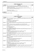
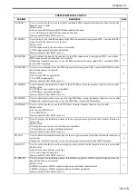
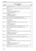
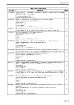
The COPIER/COUNTER screen is shown below. The items are described starting on the next page.
F-19-12
Clearing counter values
1) Select the item to clear, displaying it in reverse.
2) Press the clear key on the operation panel.
- The counter is cleared, resetting it to "00000000".
Small size and large size in this mode
- TOTAL/PICKUP/FEEDER/JAM
Large (L) size: Paper larger than A4, LTR size
Small (S) size: A4, LTR size and smaller paper
- DRBL-1/DRBL-2 (PD-PU-RL, C3-PU-RL, C4-PU-RL)
Large (L) size: Paper longer than 324 mm in the feed direction
Small (S) size: Paper 324 mm or shorter in the feed direction
- DRBL-2 (DF-PU-RL, DF-SP-PD, DF-F-BLT, DF-SP-RL)
Large (L) size: Paper longer than the LTR length (216 mm) in the feed direction
Small (S) size: Paper of the LTR length (216 mm) or shorter in the feed direction
Reading counters for consumable parts/parts needing periodic replacement
The copier has special counters (DRBL-1/DRBL-2) that can be used to provide a guideline for when to replace
consumable parts or parts needing periodic replacement.
Small size sheets are counted in increments of 1, large size sheets are counted in increments of 2.
[1]: Displays the part name. In this example, the intermediate transfer belt unit.
[2]: Displays the counter value (actual number of sheets used). The value is cleared by pressing the clear key
when the part is replaced.
<Example>
TR-BELT
/
00000201
/
00240000
/
0%
!!
000082
[1]
[2]
[3]
[4]
[5]
[6]
Summary of Contents for Color imageRUNNER C5180 Series
Page 22: ...Chapter 1 INTRODUCTION...
Page 64: ...Chapter 2 INSTALLATION...
Page 110: ...Chapter 3 BASIC OPERATION...
Page 119: ...Chapter 4 BASIC OPERATIONS AS A PRINTER...
Page 129: ...Chapter 5 MAIN CONTROLLER...
Page 138: ...Chapter 5 5 8 F 5 8 CPU HDD ROM access to the program at time of execution...
Page 165: ...Chapter 6 ORIGINAL EXPOSURE SYSTEM...
Page 209: ...Chapter 7 IMAGE PROCESSING SYSTEM...
Page 212: ...Chapter LASER EXPOSURE 8...
Page 239: ...Chapter 9 IMAGE FORMATION...
Page 324: ...Chapter 10 PICKUP FEEDING SYSTEM...
Page 435: ...Chapter 11 FIXING SYSTEM...
Page 460: ...Chapter 11 11 23 F 11 13 SEN3 SEN2 SEN1 SEN2 SEN3 SEN1 SEN2 SEN3 SEN1...
Page 491: ...Chapter 12 EXTERNALS CONTROLS...
Page 498: ...Chapter 12 12 5 F 12 2 FM1 FM7 FM9 FM2 FM13 FM14 FM12 FM11 FM10 FM5 FM3 FM4 FM8 FM6...
Page 512: ...Chapter 12 12 19 2 Remove the check mark from SNMP Status Enabled F 12 10...
Page 553: ...Chapter 13 MEAP...
Page 557: ...Chapter 14 RDS...
Page 569: ...Chapter 15 MAINTENANCE INSPECTION...
Page 578: ...Chapter 16 STANDARDS ADJUSTMENTS...
Page 597: ...Chapter 17 CORRECTING FAULTY IMAGES...
Page 612: ...Chapter 17 17 14 F 17 7 PLG1 ELCB1 SP1 H4 H3 H2 H1 H1 H2 LA1...
Page 617: ...Chapter 18 SELF DIAGNOSIS...
Page 644: ...Chapter 19 SERVICE MODE...
Page 778: ...Chapter 20 UPGRADING...
Page 823: ...Chapter 21 SERVICE TOOLS...
Page 828: ...APPENDIX...
Page 851: ......


