Chapter 19
19-124
19.6 TEST (Test Print Mode)
19.6.1 COPIER
19.6.1.1 COPIER Table
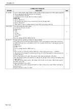
1. PG
T-19-68
COPIER>TEST>PG
Sub item
Description
level.
TYPE
Performs test print when test print type number is entered and start key is turned ON. (This
setting must always be restored to 0 after making test print.)
Setting values
0: Normal print, 0 to 100
[Factory default/After RAM clear: 0]
1
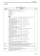
TXPH
Used to set image mode during test print output.
Setting values
0: Text mode
1: Photo mode
2: Automatic mode
3: Text/photo/map mode
4: Photographic printing paper photo mode
5: Printed photo mode
6: Text/photo mode
7: Black and white text mode
Reference:
This setting is only valid for test prints.
[Factory default/After RAM clear: 0]
1
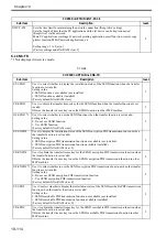
THRU
Used to select whether to use image compensation table during test print output.
Setting values
0: ON (Use)
1: OFF (Don't use)
[Factory default/After RAM clear: 0]
1
DENS-Y/M/C/K
Used to adjust density of each color for test prints (TYPE = 5).
Setting values
0 to 255: Increasing the value increases the density.
[Factory default/After RAM clear: 128]
1
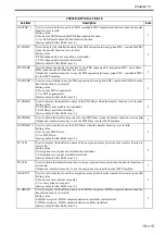
COLOR-Y/M/C/
K
Used to set output of each color for each TYPE.
For example, to set single-color M output, set "COLOR-M = 1", and make the other
settings 0 (only single colors can be output).
Setting values
0: Don't output
1: Output
[Factory default/After RAM clear: 1]
1
F/M-SW
Set it to switch over full color and mono color during PG output.
Settings
0: full color output
1: mono color output
[Factory default/After RAM clear: 0]
1
Summary of Contents for Color imageRUNNER C5180 Series
Page 22: ...Chapter 1 INTRODUCTION...
Page 64: ...Chapter 2 INSTALLATION...
Page 110: ...Chapter 3 BASIC OPERATION...
Page 119: ...Chapter 4 BASIC OPERATIONS AS A PRINTER...
Page 129: ...Chapter 5 MAIN CONTROLLER...
Page 138: ...Chapter 5 5 8 F 5 8 CPU HDD ROM access to the program at time of execution...
Page 165: ...Chapter 6 ORIGINAL EXPOSURE SYSTEM...
Page 209: ...Chapter 7 IMAGE PROCESSING SYSTEM...
Page 212: ...Chapter LASER EXPOSURE 8...
Page 239: ...Chapter 9 IMAGE FORMATION...
Page 324: ...Chapter 10 PICKUP FEEDING SYSTEM...
Page 435: ...Chapter 11 FIXING SYSTEM...
Page 460: ...Chapter 11 11 23 F 11 13 SEN3 SEN2 SEN1 SEN2 SEN3 SEN1 SEN2 SEN3 SEN1...
Page 491: ...Chapter 12 EXTERNALS CONTROLS...
Page 498: ...Chapter 12 12 5 F 12 2 FM1 FM7 FM9 FM2 FM13 FM14 FM12 FM11 FM10 FM5 FM3 FM4 FM8 FM6...
Page 512: ...Chapter 12 12 19 2 Remove the check mark from SNMP Status Enabled F 12 10...
Page 553: ...Chapter 13 MEAP...
Page 557: ...Chapter 14 RDS...
Page 569: ...Chapter 15 MAINTENANCE INSPECTION...
Page 578: ...Chapter 16 STANDARDS ADJUSTMENTS...
Page 597: ...Chapter 17 CORRECTING FAULTY IMAGES...
Page 612: ...Chapter 17 17 14 F 17 7 PLG1 ELCB1 SP1 H4 H3 H2 H1 H1 H2 LA1...
Page 617: ...Chapter 18 SELF DIAGNOSIS...
Page 644: ...Chapter 19 SERVICE MODE...
Page 778: ...Chapter 20 UPGRADING...
Page 823: ...Chapter 21 SERVICE TOOLS...
Page 828: ...APPENDIX...
Page 851: ......


