Chapter 5
5-31
5.7.8 SRAM PCB
5.7.8.1 Preparation for Removing the
SRAM PCB
1) Remove the rear upper cover.
Reference[Removing the Rear Upper Cover]
2) Remove the rear left cover (upper).
Reference[Removing the Rear Left Cover
(Upper)]
3) Remove the left rear cover (upper).
Reference[Removing the Left Rear Cover
(Upper)]
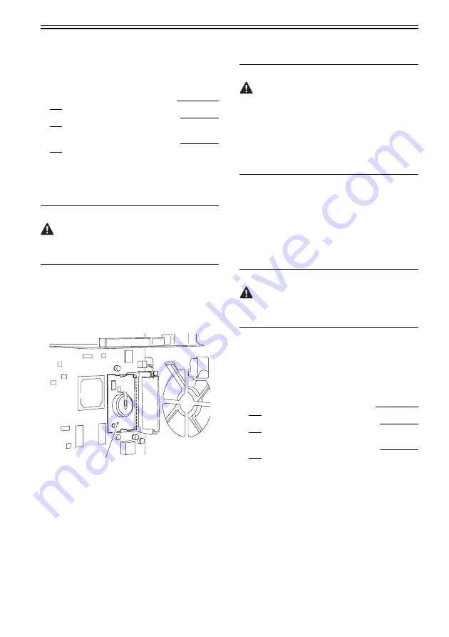
5.7.8.2 Removing the SRAM PCB
1) Remove the main controller box cover [3].
(Referring to Procedure 5.7.3.2)
Points to Note When Removing the HDD
Take care to avoid static damage when removing the
HDD.
It is also important to protect the HDD from impact.
2) Remove the HDD [4].
(Referring to Procedure 5.7.11)
3) Remove the 2 HDD mounting plates [2].
(Referring to Procedure 5.7.7.2)
4) Remove the SRAM PCB [1].
F-5-46
5.7.8.3 When Replacing the SRAM PCB
When the SRAM PCB is replaced, all data in its
memory will be lost (file-related, user mode-related,
service mode-related, history-related files). There
will be no error operation, and initialization will take
place automatically.Å@
If you pull out the SRAM PCB from machine B and
mount it to machine A, the PCB will be initialized
and be rendered useless for machine A or B. Take
full care.
1) When you turn on the power after replacing the
SRAM PCB, the machine will perform automatic
initialization and will indicate a message on its
panel to the effect that you are to turn off and then
on the power switch found on its right side.
Follow the message and turn off and then on the
machine.
2) Using service mode, initialize the RAM.
COPIER>FUNCTION>CLEAR>MN-CON
Inform the user that the following steps will result in
the loss of all image data in the Box before starting
the work.
5.7.9 Boot ROM PCB
5.7.9.1 Preparation for Removing the Boot
ROM PCB
1) Remove the rear upper cover.
Reference[Removing the Rear Upper Cover]
2) Remove the rear left cover (upper).
Reference[Removing the Rear Left Cover
(Upper)]
3) Remove the left rear cover (upper).
Reference[Removing the Left Rear Cover
(Upper)]
[1]
Summary of Contents for Color imageRUNNER C5180 Series
Page 22: ...Chapter 1 INTRODUCTION...
Page 64: ...Chapter 2 INSTALLATION...
Page 110: ...Chapter 3 BASIC OPERATION...
Page 119: ...Chapter 4 BASIC OPERATIONS AS A PRINTER...
Page 129: ...Chapter 5 MAIN CONTROLLER...
Page 138: ...Chapter 5 5 8 F 5 8 CPU HDD ROM access to the program at time of execution...
Page 165: ...Chapter 6 ORIGINAL EXPOSURE SYSTEM...
Page 209: ...Chapter 7 IMAGE PROCESSING SYSTEM...
Page 212: ...Chapter LASER EXPOSURE 8...
Page 239: ...Chapter 9 IMAGE FORMATION...
Page 324: ...Chapter 10 PICKUP FEEDING SYSTEM...
Page 435: ...Chapter 11 FIXING SYSTEM...
Page 460: ...Chapter 11 11 23 F 11 13 SEN3 SEN2 SEN1 SEN2 SEN3 SEN1 SEN2 SEN3 SEN1...
Page 491: ...Chapter 12 EXTERNALS CONTROLS...
Page 498: ...Chapter 12 12 5 F 12 2 FM1 FM7 FM9 FM2 FM13 FM14 FM12 FM11 FM10 FM5 FM3 FM4 FM8 FM6...
Page 512: ...Chapter 12 12 19 2 Remove the check mark from SNMP Status Enabled F 12 10...
Page 553: ...Chapter 13 MEAP...
Page 557: ...Chapter 14 RDS...
Page 569: ...Chapter 15 MAINTENANCE INSPECTION...
Page 578: ...Chapter 16 STANDARDS ADJUSTMENTS...
Page 597: ...Chapter 17 CORRECTING FAULTY IMAGES...
Page 612: ...Chapter 17 17 14 F 17 7 PLG1 ELCB1 SP1 H4 H3 H2 H1 H1 H2 LA1...
Page 617: ...Chapter 18 SELF DIAGNOSIS...
Page 644: ...Chapter 19 SERVICE MODE...
Page 778: ...Chapter 20 UPGRADING...
Page 823: ...Chapter 21 SERVICE TOOLS...
Page 828: ...APPENDIX...
Page 851: ......