6
5
4
3
2
1
Color Image Reader-F1
Service Manual
October 10, 2012
Revision 1.1
Product Outline
Technology
Periodic Servicing
Parts Replacement and Cleaning Procedure
Adjustment
Installation
Appendix
Page 1: ...6 5 4 3 2 1 Color Image Reader F1 Service Manual October 10 2012 Revision 1 1 Product Outline Technology Periodic Servicing Parts Replacement and Cleaning Procedure Adjustment Installation Appendix ...
Page 2: ...information as the need arises In the event of major changes in the contents of this manual over a long or short period Canon will issue a new edition of this manual The following paragraph does not apply to any countries where such provisions are inconsistent with local law Trademarks The product names and company names used in this manual are the registered trademarks of the individual companies...
Page 3: ...switch closing the front door and closing the delivery unit door which results in supplying the machine with power 2 In the digital circuits 1 is used to indicate that the voltage level of a given signal is High while 0 is used to indicate Low The voltage value however differs from circuit to circuit In addition the asterisk as in DRMD indicates that the DRMD signal goes on when 0 In practically a...
Page 4: ...Blank Page ...
Page 5: ...dic Servicing List of Work for Scheduled Servicing Reader 3 2 List of Work for Scheduled Servicing ADF 3 4 4 Parts Replacement and Cleaning Procedure Parts replacement and cleaning procedure 4 2 Removing the Reader Controller PCB 4 2 Cleaning the Reader Scanner Mirors 4 4 Removing the Reader Scanner Unit 4 6 List of Parts ADF 4 10 External Covers 4 10 Consumable Parts Requiring Periodic Replacemen...
Page 6: ...rview ADF 5 6 Adjustment Method ADF 5 6 Preparation or Creation of Test Chart 5 6 Adjusting the Height of the hinge 5 7 Adj of DADF Tray width 5 9 Adjusting the Perpendicularity 5 10 Scan position auto adj in DADF mode 5 11 Adj img pstn in DADF mode horz scan 5 11 Adj of DADF img lead edge margin front 5 12 Fine adj of DADF image magnifictn front 5 12 White level adj 5 13 6 Installation How to che...
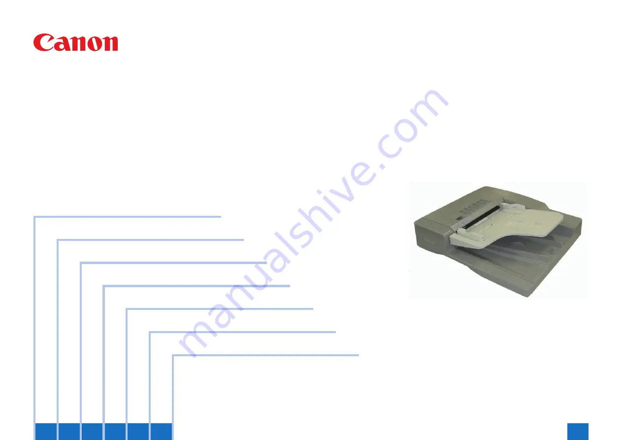
Page 7: ...1 1 Product Outline Product Outline Features Reader Specifications Reader Names of Parts Reader Features ADF Specifications ADF Names of Parts ADF ...
Page 8: ...Gradation 256 gradations Carriage position detection Scanner Unit HP Sensor PS2 Magnification change 25 to 400 B W scan magnification change Vertical 2 line skipping 25 to 50 Color digital reproduction In horizontal direction Image processing in main controller PCB In vertical direction Image processing in main controller PCB Some are processed by the reader controller PCB Number of line of Readin...
Page 9: ...ss Section Names of Parts Reader External View Reader PCB Cover Glass Retainer Right Glass Retainer Center Glass Retainer Left Reader Right Cover Reader Front Cover Reader Rear Cover Copyboard Glass Stream Read Glass Reader Left Cover F 1 1 Cross Section Copyboard Glass Stream Read Glass Scanner Unit F 1 2 ...
Page 10: ...cument size AB type B6 A5 B5 A4 A5R A4R B4 A3 B6 Cross feed only INCH type STMT LTR LTRR LGL 11 17 SMTR B5R 8K 16K Document width 140 297mm Document length longitudinal 128 432mm 630mm is held by the operator Document tray capacity 100 sheets 80g m2 Document processing mode Single sided document processing Double sided document processing Document size recognition Available Standard size Mixed doc...
Page 11: ...nt delivery tray Slide guide F 1 3 Cross Section 13 12 3 5 4 6 7 8 9 10 15 14 1 2 11 1 Lower registration roller 2 Upper registration roller 3 Feed roller 4 Separation pad unit 5 Pickup roller 6 Document supply tray 7 Upper delivery reversal roller 8 Lower delivery reversal roller 9 Read roller 2 lower 10 Read roller 2 upper 11 Platen roller 12 White sheet 13 Read roller 14 Read roller 1 lower 15 ...
Page 12: ...2 2 Technology Technology Basic Configuration Reader Controls Basic Configuration ADF Controls ADF ...
Page 13: ...on specification Scanner motor M1 2 phase pulse motor pulse control Scanner unit exhaust fan FM1 Exhaustion of scanner unit Scanner unit cooling fan FM2 Cooling of scanner unit DADF open closed sensor 1 SR1 DADF open detection DADF is detected at 5 degree Scanner unit HP sensor SR2 Scanner unit HP detection DADF open closed sensor 2 SR3 DADF open detection size detection timing is detected when DA...
Page 14: ... Lens Green G line Blue B line Black White B W line F 2 2 LED lamp unit On LED lamp unit the light is generated from the 2 LED lamp PCBs LED chip 48 pieces per PCB Generated light is exposed to the original through the reflection plate New lenses By using the Lens Unit with 4 lenses combined a compact Scanner Unit is achieved Reading sensor Reading sensor scans the image per 1 image line Reading s...
Page 15: ... Digital magnification process on the main controller PCB 2 25 to 50 50 1 to 199 9 100 to 200 T 2 2 Detecting the Size of Originals Overview The machine identifies the original size by the combination of measurement result of reflection light from the reflection sensor and specific points of CCD Also to identify it accurately even though an original moves when ADF is closed the machine measures 2 ...
Page 16: ...n 2 Original detection position 3 Original detection position 4 Original detection position 5 Original detection position 6 F 2 3 IDirt Sensor Control Overview When reading an original original reading position is changed according to the presence absence of dust on the Stream Reading Glass or the Guide Plate of the ADF on the Platen Roller in case of the reverse model or image correction is perfo...
Page 17: ...presence absence of dust is detected at all positions A B and C in that order The position where dust is least present is used as the reading position and reading starts C B A F 2 5 Between sheets The Scanner Unit does not move It reads the original using the position determined at the end or start of a job however if the presence of dust is still detected at the position the machine will execute ...
Page 18: ...ation clutch CL2 Stamp solenoid SL2 ADF Fan FM1 Pressurization solenoid SL1 ADF driver PCB PCB1 LED PCB PCB3 Different width sensor PCB PCB4 F 2 7 Roller Layout 11 3 5 4 6 7 8 9 13 12 1 2 10 1 2 3 4 5 6 7 8 9 Lower registration roller Upper registration roller Feed roller Separation pad unit Pickup roller Upper delivery reversal roller Lower delivery reversal roller Read roller 2 lower Read roller...
Page 19: ... 2 Document size detection length SR11 Release motor HP sensor Release motor HP detection YES SR12 Document width sensor 1 Document size detection width SR13 Document width sensor 2 Document size detection width SR14 Document width sensor 3 Document size detection width SR15 Document width sensor 4 Document size detection width VR1 Document width volume Document size detection width F 2 9 T 2 3 Dr...
Page 20: ...name Outline of operation Associated print mode Forward pickup delivery Picks up reads and then delivers a document Single sided document Simplex printing Single sided document Duplex printing Forward feed reverse delivery Picks up reads reverses and delivers a document Double sided document Duplex printing Double sided document Simplex printing The document flows as shown below F 2 11 T 2 5 Forwa...
Page 21: ...very of first document sheet Completion of delivery of second document sheet Start of reading of second document sheet End ob job F 2 13 Forward Pickup Reverse Delivery Operation Duplex read operation when two document sheets are placed Document To next Pickup and formation of loop of first document sheet Waiting for reading of the first document Start of reading of front side of first document sh...
Page 22: ... Idle feed of first document sheet Removal of idle registration loop of first document sheet and release of re pickup and delivery roller End of reading of reverse side of first document sheet and pressurization of delivery roller F 2 15 To next Start of separation of second document sheet and pressurization of delivery roller Start of reading of top side of second document sheet End of reading of...
Page 23: ...h a document placed on the document tray pressing the print start key will pick up the document in the following manner Pickup operation When the pickup feed motor M1 turns in reverse direction the pickup roller unit lowers to rotate the pickup rollers thus feeding the document The stopper rises in conjunction with the pickup roller unit The separation sheet and pad are used to prevent multiple sh...
Page 24: ...ing the platen roller The read image is stored in the memory of the host machine Platen roller LED Read roller 2 Read glass M1 F 2 20 F 2 21 Pickup Unit and Stopper The pickup unit consists of a pickup roller and feed roller When the print start key is pressed or a document pickup signal is input the pickup feed motor M1 turns in the reverse direction to lower the pickup unit via the pickup clutch...
Page 25: ...y unit Platen roller Read roller 2 Read roller 1 Delivery reversal roller M1 S L 2 M1 S L 2 F 2 23 Reversal feed 1 When the trailing edge of the fed document moves past the delivery reversal sensor SR3 the pickup feed motor stops Immediately after this the pickup feed motor starts turning in the reverse direction to feed the document to the registration roller then it stops At this time the pressu...
Page 26: ...ally pressurized the Shift solenoid SL2 turns on only when the document is reversed for duplex printing S L 2 S L 2 M1 M1 Delivery reversal roller Reading position F 2 26 Release Operation When a document is read the read roller 1 lower driven rollers are pressurized released to prevent the training edge of the document from swaying After separation of the document the read roller 1 lower driven r...
Page 27: ...he following three document detection functions are used Function Description Description Document presence absence detection Detects whether there is a document on the document pickup tray Document set sensor SR5 Document length detection Detects the document length according to the distance from the position where the read sensor SR2 turns on to the position where the read sensor SR2 turns off R...
Page 28: ...ON B4 B4 LDR ON OFF B4 B4 LDR ON ON B4 B4 LDR W 200 OFF OFF OFF A5 A5 STMT OFF ON A5 A5 LGL ON OFF A4R A4R LTRR ON ON A4R A4R LGL ON OFF OFF A5 A5 STMT OFF ON A5 A5 LGL ON OFF A4R A4R LTRR ON ON A4R A4R LGL W 172 OFF OFF B6 B6 STMT OFF ON B6 B6 LGL ON OFF B5R B5R LTRR ON ON B5R B5R LGL W 138 5 OFF OFF OFF A5R A5R STMT OFF ON A4R B4 STMT ON OFF A5R A5R STMT ON ON A4R B4 STMT ON OFF OFF A5R A5R STMT...
Page 29: ...es No No No A4R 210 Yes No No A5 No Yes No B5R 182 No B6 No b INCH type Mixed Different series of size LGL LTRR STMT STMTR Maximum size Width 215 9 139 7 LDR 279 Yes No No No LTR Yes No Yes No LGL 215 9 No LTRR No STMT No Contents Yes Combination assured No Possible to feed but not assured No Possible to have original jam No Out of Specifications T 2 9 T 2 10 T 2 11 Detecting Jams Jams This machin...
Page 30: ...r open closed sensor 2 Reader 01 0092 COVER OP Cover open closed sensor SR6 01 0093 COVER OP Cover open closed sensor SR6 01 0094 RESIDUAL Registration sensor Read sensor Delivery reversal sensor SR1 SR2 SR3 01 0095 PICKUP NG Power Supply Power Supply The power supply lines are shown below This machine is powered via two power supply lines 24 V and 12 V from the reader controller PCB The 12 V powe...
Page 31: ...llowing adjustment items Carry out each adjustment after replacing the relevant parts Adjustment type Parts to replace Remarks Reference Adjusting the Height of the hinge Hinge p 5 7 Adj of DADF Tray width Slide guide and document width volume p 5 9 Adjusting the Perpendicularity Hinge p 5 10 Scan position auto adj in DADF mode Platen roller p 5 11 Adj img pstn in DADF mode horz scan During instal...
Page 32: ... 2 35 Periodic Servicing When the parts are reaching the expected service life perform the parts replacement or cleaning etc if needed Item Part name Expected service life Operation Reference Periodically replaced parts No Durables parts Pickup roller unit 80 000 sheets Replace ment p 4 20 Separation pad p 4 20 Stamp 7 000 times p 4 21 Hinge unit left 150 000 times The coming and going opening and...
Page 33: ...3 3 Periodic Servicing Periodic Servicing List of Work for Scheduled Servicing Reader List of Work for Scheduled Servicing ADF ...
Page 34: ... the glass surface 2 Stream reading glass Surface FL2 9620 000 1 CL Use Oil Glass Cleaner FY9 6020 Do Not use alcohol Stream reading glass Surface Back 1 CL Including the white plate positioning of the glass surface 3 Scanner rail shaft CL LU SHC Oil FY9 6029 CAUTION Cleaning the Stream Reading Glass with alcohol results in thinning of the oil film on the surface As a result the frictional resista...
Page 35: ...3 3 3 3 3 3 Periodic Servicing List of Work for Scheduled Servicing Reader Periodic Servicing List of Work for Scheduled Servicing Reader Scanner shaft Scanner shaft Scanner rail Scanner rail F 3 2 ...
Page 36: ...oller 1 CL 5 Feed guide dust collection tape FL3 2942 1 CR CL 6 Upper delivery reversal roller 1 CL 7 Lower delivery reversal roller 1 CL Hinge unit left FE2 1598 1 CR 150 000 times The coming and going opening and shutting number of times 4 2 Stamp FC7 5465 1 CR 7 000 times User Maintenance 4 2 White plate pressure plate 1 CL Platen roller 1 CL White sheet 1 CL Various rollers driven rollers CL V...
Page 37: ...4 4 Parts Replacement and Cleaning Procedure Parts Replacement and Cleaning Procedure Parts Replacement and Cleaning Procedure ...
Page 38: ...ment and cleaning procedure Removing the Reader Controller PCB Procedure 1 Open the 2 Hinge Covers 1 and remove the 2 Open Close Guide Plates 2 4 Screws 3 x4 1 2 3 2 3 2 Open the ADF Unit 3 Remove the Reader Cable Cover 1 2 Screws 2 x2 2 1 F 4 1 F 4 2 4 Disconnect the connector 1 from the Reader Controller PCB 5 Remove the 2 Flat Cables 2 from the Reader Controller PCB 2 Connectors with a hook x3 ...
Page 39: ...d cleaning procedure Removing the Reader Controller PCB Procedure 7 Remove the Reader Controller PCB Cover Plate 1 4 Screws 2 x4 2 1 2 8 Remove the Flat Cable 2 from the Reader Controller PCB 1 1 Connector with a hook 9 Remove the Reader Controller PCB Unit 2 Edge Saddles 4 4 Connectors 3 4 Screws 5 x4 x5 x2 1 5 5 2 3 3 4 4 F 4 5 F 4 6 10 Remove the Reader Controller PCB 1 4 Screws 2 x4 1 2 2 F 4 ...
Page 40: ...s Procedure 1 Remove the ADF Unit 1 2 Pull out the Control Panel 2 and remove the Front Cover 3 2 Screws 4 2 Bosses 5 1 Hook 6 x2 2 1 3 3 F 4 8 CAUTION Grease is applied on the 2 Rail Shafts 1 of the Reader Scanner Unit If you have touched the grease be careful not to put it to other parts 1 3 Move the belt 1 and move the Reader Scanner Unit 2 to the cut off of the Reader Unit 2 3 2 1 4 Loosen the...
Page 41: ...leaning Procedure Parts replacement and cleaning procedure Cleaning the Reader Scanner Mirors Procedure Loosen x2 1 F 4 10 6 Move the Reader Scanner Unit in the direction of the arrow while paying attention not to make it contact with the frame of the Reader and place it as shown in the figure below 1 1 7 Remove the LED Unit 1 2 Connectors 2 1 2 x2 F 4 11 F 4 12 ...
Page 42: ...re Removing the Reader Scanner Unit Procedure 8 Return the Scanner Unit to its original position 9 Clean the 4 mirors 1 1 1 2 NOTE The rearmost mirror 2 cannot be cleaned However it is a dustproof mirror so there is no need to clean it F 4 13 Removing the Reader Scanner Unit Procedure 1 Remove the ADF Unit 1 2 Pull out the Control Panel 2 and remove the Front Cover 3 2 Screws 4 2 Bosses 5 1 Hook 6...
Page 43: ...t If you have touched the grease be careful not to put it to other parts 1 3 Move the belt 1 and move the Reader Scanner Unit 2 to the cut off of the Reader Unit 2 3 2 1 4 Loosen the screw to release the tension applied on the belt After that remove the belt 1 from the Reader Scanner Unit 2 F 4 15 2 1 Loosen CAUTION Holding the Reader Scanner Unit Be sure to hold both edges 1 Do not touch the PCB ...
Page 44: ... Procedure Parts replacement and cleaning procedure Removing the Reader Scanner Unit Procedure 2 1 6 Disconnect the Flat Cable 1 with Protection Sheet 2 from the Reader Scanner Unit 1 Connector with a hook 3 Guide A 1 3 2 A CAUTION When connecting the Flat Cable be sure to insert the 4 protrusions 2 of the Flat Cable Protection Sheet 1 into the Guide A A 1 2 2 F 4 17 ...
Page 45: ...g the Reader Scanner Unit Procedure Parts Replacement and Cleaning Procedure Parts replacement and cleaning procedure Removing the Reader Scanner Unit Procedure Installation Procedure When installing the belt to the Reader Scanner Unit it can be installed easily by removing the belt from pulley F 4 18 ...
Page 46: ... small cover Front cover Feeder cover No Part name Part number Reference 1 Front cover Refer to page 4 15 2 Rear cover Refer to page 4 16 3 Feeder cover Refer to page 4 16 4 Rear small cover F 4 19 T 4 1 Consumable Parts Requiring Periodic Replacement and Cleaning Points 4 1 3 2 No Part name Part number Reference 1 Pickup roller unit FM0 1226 Refer to page 4 20 2 Separation pad FL2 9942 Refer to p...
Page 47: ... No Part name Part number Reference M1 ADF motor M2 Release motor SL1 Pressurization solenoid SL2 Stamp solenoid CL1 Registration clutch CL2 Pickup clutch PCB1 ADF controller PCB PCB3 Document set LED PCB PCB4 Different width sensor PCB FM1 Fan F 4 21 T 4 3 Others Platen roller Left hinge Right hinge Part name Part number Reference Left hinge Refer to page 4 32 Right hinge Refer to page 4 33 Plate...
Page 48: ... Part name Part number Reference SR1 Registration sensor SR2 Read sensor SR3 Delivery reversal sensor SR4 Timing sensor SR5 Document set sensor SR6 Cover open closed sensor SR7 Document length sensor 1 SR8 A4R LTRR identification sensor SR10 Document length sensor 2 SR11 Release motor HP sensor SR12 Document width sensor 1 SR13 Document width sensor 2 SR14 Document width sensor 3 SR15 Document wid...
Page 49: ...ont Cover page 4 15 4 Remove the feeder cover Removing the Feeder Cover page 4 16 5 Remove the tray holder Screw 1 pc x1 6 Unload the cable harness from the cable guide Connector 2 pcs Screw 1 pc x2 x1 F 4 24 F 4 25 7 Remove the rear cover Removing the Rear Cover page 4 16 8 Disconnect the eight connectors from the ADF driver PCB x8 9 Remove the document tray Connector 1 pc Screw 1 pc x1 x1 10 Rem...
Page 50: ...nits ADF Removing the Feed Unit 12 Remove the harness guide Connector 5 pcs Screw 1 pc x1 x5 13 Remove the pickup clutch registration clutch Pickup Clutch Registration Clutch CL1 CL2 page 4 23 14 Remove the feed unit Screw 7 pcs x7 F 4 28 F 4 29 CAUTION When install ADF to a host machine after exchange work adjustment of eight items is need ...
Page 51: ...Removing the Front Cover Parts Replacement and Cleaning Procedure External Covers ADF Removing the Front Cover External Covers ADF Removing the Front Cover 1 Open the feeder cover 2 Remove the screw x1 F 4 30 F 4 31 3 Open the ADF 4 Remove the front cover Screw 2 pcs x2 F 4 32 ...
Page 52: ...st machine and detach the rear small cover Screw 1 pc x1 3 Remove the rear cover Screw 2 pcs x2 CAUTION Remove the rear cover with the two claws released F 4 33 F 4 34 Removing the Feeder Cover 1 Open the feeder cover 2 Remove the rear cover and rear small cover Removing the Rear Cover page 4 16 3 Unload the cable harness Connector 1 pc Screw 1 pc Clamp 2 pcs x1 x1 4 Open the ADF 5 Remove the fron...
Page 53: ...the inner cove 7 Remove the feeder cover Screw 1 pc Positioning pin 1 pc x1 NOTE When moving the feeder cover with care to the rear cable hareness F 4 36 Removing the inner cove 1 Open the feeder cover 2 Remove the inner cover from the feeder cover Hook 2 pcs x2 CAUTION When attaching the innaer cover check that the sensor flag appears from an inner cover F 4 37 F 4 38 ...
Page 54: ...e Removing the white plate 1 Open the ADF 2 Remove the white plate 6 Place the white plate on the copyboard glass by aligning it with the index sheet F 4 39 F 4 40 7 Close the DADF and then open it again 8 Press the white plate upward as shown in the figure below CAUTION If the white plate is pressed downward it is placed on the index sheet so be sure to press it upward F 4 41 F 4 42 ...
Page 55: ...h the DADF closed check that the white plate is not placed on the Index sheet as shown in the figures CAUTION Be sure that there is no gap between the white plate and the index sheet As a guide it should be 0 3 mm or less White plate DADF White plate DADF White plate DADF White plate DADF Index Sheet Index Sheet Index Sheet Index Sheet Reader Unit Reader Unit Reader Unit Reader Unit F 4 43 ...
Page 56: ...nt and Cleaning Points ADF Removing the Pickup Roller Unit 1 Open the feeder cover 2 Remove the inner cover from the feeder cover 3 Remove the pickup roller unit Resin ring 2 pcs Bearing 2 pcs NOTE When replacing the consumable parts be sure to clear the parts counter Lv1 COPIER COUNTER DRBL 2 DF PU RL F 4 44 Removing the Separation Pad 1 Open the feeder cover 2 Remove two hooks to remove the sepa...
Page 57: ...he like attach a new stamp Be sure to attach the new stamp with the stamp face up 4 Close the feeder cover and separation guide CAUTION If the stamp is floating a jam can occur Be sure to push in the stamp until it clicks NOTE When replacing the consumable parts be sure to clear the parts counter Lv1 COPIER COUNTER DRBL 2 STAMP F 4 46 Exchanging the Feed Guide 1 Open the ADF 2 Remove the feed guid...
Page 58: ...ving the ADF Motor M1 1 Open the feeder cover 2 Remove the rear cover Removing the Rear Cover page 4 16 3 Remove the ADF motor unit Connector 1 pc Tension spring 1 pc Screw 3 pcs x3 F 4 48 Removing the Release Motor M2 1 Open the feeder cover 2 Open the ADF 3 Detach the front cover Removing the Front Cover page 4 15 4 Close the ADF 5 Remove the release motor support plate Connector 2 pcs Screw 5 p...
Page 59: ...gistration Clutch CL1 CL2 Removing the Pressurization Solenoid SL1 1 Open the feeder cover 2 Remove the rear cover Removing the Rear Cover page 4 16 3 Remove the pressurization solenoid Connector 1 pc Screw 2 pcs x2 x1 F 4 51 Pickup Clutch Registration Clutch CL1 CL2 1 Open the feeder cover 2 Remove the rear cover Removing the Rear Cover page 4 16 3 Remove the clutch support plate Connector 2 pcs ...
Page 60: ...egistration clutch with the gear black aligned with the mark B black on the clutch support plate White Black CL1 CL2 W B F 4 53 Removing the ADF Driver PCB1 1 Open the feeder cover 2 Remove the rear cover and rear small cover Removing the Rear Cover page 4 16 3 Remove the ADF driver PCB Connector 12 pcs ALL Screw 2 pcs x2 x12 Removing the LED PCB PCB3 1 Open the feeder cover 2 Open the ADF 3 Remov...
Page 61: ...nsor PCB PCB4 7 Remove the LED PCB Screw 1 pc Connector 1 pc x1 x1 F 4 56 Removing the Different Width Sensor PCB PCB4 1 Open the feeder cover 2 Open the DADF 3 Remove the front cover Removing the Front Cover page 4 15 4 Close the DADF 5 Remove the inner cover Removing the inner cove page 4 17 6 Remove the different width sensor holder Screw 3pcs x3 7 Remove the different width sensor PCB Connecto...
Page 62: ... Sensor SR1 SR2 SR3 Removing the Fan 1 Open the feeder cover 2 Remove the rear cover Removing the Rear Cover page 4 16 3 Remove the fan Screw 1 pc Connector 1 pc x1 x1 CAUTION Install the fan with the arrow oriented as shown F 4 59 F 4 60 Removing the Sensor SR1 SR2 SR3 1 Remove the feed unit Removing the Feed Unit page 4 13 2 Remove the metal plate Screw 3 pcs x3 3 Remove the two timing belts F 4...
Page 63: ...t and Cleaning Procedure Clutch Solenoid Motor Fan PCB ADF Removing the Sensor SR1 SR2 SR3 4 Remove the resin ring pulley gear E ring and bearing A position Remove the support plate three gears and bearing A x1 F 4 63 5 While pushing the hook in the direction of the arrow remove the platen roller unit in the direction of the arrow F 4 64 ...
Page 64: ...B ADF Removing the Sensor SR1 SR2 SR3 Parts Replacement and Cleaning Procedure Clutch Solenoid Motor Fan PCB ADF Removing the Sensor SR1 SR2 SR3 6 Remove the cover Screw 2 pcs x2 F 4 65 7 Remove the read roller 2 Resin ring 1 pc Pulley 1 pc Gear 2 pcs E ring 1 pc Bearing 3 pcs F 4 66 ...
Page 65: ...or mount Hook 2 pcs Screw 2 pcs x2 Hook 9 Remove the sensor SR1 SR2 SR3 Connector 1 pc SR1 SR2 SR3 x1 F 4 67 F 4 68 Removing the Timing Sensor SR4 1 Open the feeder cover 2 Remove the rear cover Removing the Rear Cover page 4 16 3 Remove the timing sensor Connector 1 pc x1 Removing the Document Set Sensor SR5 1 Open the feeder cover 2 Remove the rear cover Removing the Rear Cover page 4 16 3 Remov...
Page 66: ...the Document Length Sensor SR7 SR10 Removing the Cover Open Closed Sensor SR6 1 Open the feeder cover 2 Remove the rear cover Removing the Rear Cover page 4 16 3 Remove the cover open closed sensor Connector 1 pc x1 F 4 71 Removing the Document Length Sensor SR7 SR10 1 Detach the cover on the reverse side of the document tray Screw 3 pcs x3 2 Remove the document length sensor Connector 1 pc x1 SR7...
Page 67: ...ay Refer to page 4 30 2 Remove the A4R LTRR Identification Sensor Connector 1 pc Screw 2 pcs SR8 3 2 2 1 x1 x2 CAUTION Install the document width volume with its lower gear groove 1 fitting on the projection 2 on the document tray side Be sure to install it with the arrow on the gear aligned with the arrow 3 on the tray cover F 4 74 Removing the Release Motor HP Sensor SR11 1 Open the feeder cover...
Page 68: ...crew 2 pcs 3 2 2 1 x2 x2 VR1 3 Remove the document width volume Hexagon NUT 1pc Washer 1 pc CAUTION Install the document width volume with its lower gear groove 1 fitting on the projection 2 on the document tray side Be sure to install it with the arrow on the gear aligned with the arrow 3 on the tray cover F 4 76 Removing the hinge Removing the left hinge 1 Remove the DADF from the host machine 2...
Page 69: ... Platen roller Removing the Right hinge 1 Remove the DADF from the host machine 2 Reverse ADF 3 Remove the Right hinge Screw 2 pcs x2 CAUTION When install DADF to a host machine after exchange work adjustment of eight items is need F 4 78 Removing the Platen roller 1 Remove the feed unit Removing the Feed Unit page 4 13 2 Remove the metal plate Screw 3 pcs x3 3 Remove the two timing belts F 4 79 F...
Page 70: ...t and Cleaning Procedure Clutch Solenoid Motor Fan PCB ADF Removing the Platen roller 4 Remove the resin ring pulley gear E ring and bearing A position Remove the support plate three gears and bearing A x1 F 4 81 5 While pushing the hook in the direction of the arrow remove the platen roller unit in the direction of the arrow F 4 82 ...
Page 71: ...ts Replacement and Cleaning Procedure Clutch Solenoid Motor Fan PCB ADF Removing the Platen roller 7 Remove the Platen roller Resin ring 1 pc Platen roller holder left 1 pc Platen roller holder right 1 pc Screw 2 pcs CAUTION When install DADF to a host machine after exchange work adjustment of eight items is need F 4 83 ...
Page 72: ...5 5 Adjustment Adjustment Adjustment Reader Overview ADF Adjustment Method ADF ...
Page 73: ...ON SYSTEM 2 RSRAMBUP Restoration Lv COPIER FUNCTION SYSTEM 2 RSRAMRES NOTE When changing the service mode setting values it is recommended to back them up in the above service mode Performing backup makes the work easier when replacing the Reader Controller PCB etc T 5 1 T 5 2 Measurement during Reader Controller PCB Replacement and After RAM Clear Points to note before replacing the Reader Contro...
Page 74: ... COPIER ADJUST PASCAL 1 OFST P Y OFST P M OFST P C OFST P K 5 Perform the MTF filter coefficient computation Lv COPIER FUNCTION CCD 1 MTF CLC 6 Perform computation for front back linearity matching Lv COPIER FUNCTION CCD 1 DF LNR 7 Enter the values written on the service label on the back of the Reader Front Cover Lv FEEDER ADJUST 1 DOCST LA SPEED DOCST2 LA SPD2 T 5 5 T 5 6 T 5 7 T 5 8 8 Adjust tr...
Page 75: ...4 F 5 1 T 5 15 3 2 Perform service mode item Lv COPIER FUNCTION CCD 1 DF WLVL1 3 3 Remove the paper from copyboard glass set it in the DADF document pickup tray 3 4 Perform service mode item Lv COPIER FUNCTION CCD 1 DF WLVL2 3 5 Again Set A4 or LTR paper in the copyboard glass close the DADF 3 6 Perform service mode item Lv COPIER FUNCTION CCD 1 DF WLVL3 3 7 Remove the paper from copyboard glass s...
Page 76: ...ent pickup tray 3 4 Perform service mode item T 5 23 F 5 2 T 5 24 T 5 25 Lv COPIER FUNCTION CCD 1 DF WLVL2 3 5 Again Set A4 or LTR paper in the copyboard glass close the DADF 3 6 Perform service mode item Lv COPIER FUNCTION CCD 1 DF WLVL3 3 7 Remove the paper from copyboard glass set it in the DADF document pickup tray 3 8 Perform service mode item Lv COPIER FUNCTION CCD 1 DF WLVL4 4 Perform the M...
Page 77: ...uto adj in DADF mode Platen roller p 5 11 Adj img pstn in DADF mode horz scan During installation only p 5 11 Adj of DADF img lead edge margin front During installation only p 5 12 Fine adj of DADF image magnifictn front Motor roller p 5 12 White level adjt Platen roller p 5 13 CAUTION Carry out all the above adjustments after removing the ADF from the reader unit T 5 32 Adjustment Method ADF Prep...
Page 78: ...left hinge height 2 Adjust the right hinge height 3 Adjust the left hinge height 4 Adjust or check the right hinge height F 5 4 Check the height of the left hinge 1 Checking the rear left height of the ADF Cut a sheet of A4 paper use plain paper to make a paper slip with width of 45mm Set paper against the protrusions of the stream reading glass in such a manner that the seat of the stream reading...
Page 79: ...4 Pulling out the set paper Pull out the paper in the direction of the arrow to check that you feel slight resistance Check the height of the right hinge 1 When the ADF is closed the document hold sheet must be in contact with the document glass F 5 7 F 5 8 Adjust the height of the left hinge 1 Adjust the height with the left hinge height adjusting screw CAUTION Loosen the lock nut before adjustme...
Page 80: ...ke previous ADFs you will need to make this adjustment at time of installation so that you will be able to store its result in the reader unit If you omit this adjustment the following will likely occur wrong original size detection AB Configuration Adjustment 1 Start service mode 2 Touch the following notations in sequence to bring up the Adjustment screen LV 1 FEEDER FUNCTION TRY A4 3 Adjust the...
Page 81: ...his manual Copy it or clip it out 2 Check the perpendicularity at the leading edges of the test chart and copy Measure dimensions A and B on the test chart and dimensions A and B on the copy If it is not A B A B go through steps 3 and later B A Test chart B A feed direction Copy feed direction F 5 11 3 Loosen the screw securing the right hinge A B Slide the hinge of the ADF forward B A Slide the h...
Page 82: ...e then execute auto adjustment once again 2 If the auto adjustment operation still fails start service mode and make adjustments manually LV 1 COPIER ADJUST ADJ XY STRD POS Adj img pstn in DADF mode horz scan 1 Place the test chart in the ADF and make a copy 2 Compare the copy against the Test Chart for the horizontal registration as necessary make the following adjustments 3 On the Service Mode s...
Page 83: ...ON After completion of this adjustment check the perpendicularity If the perpendicularity is not within spec adjust it again following the procedures mentioned in Adjusting the Perpendicularity and later F 5 15 Fine adj of DADF image magnifictn front 1 Place the Test Chart in the ADF and make a copy Refer to the output as copy A 2 Compare Test Chart and copy A in terms of the length of the image i...
Page 84: ...d by the user on the copyboard glass and close the ADF 3 Press DF WLVL1 to highlight 4 Press OK Automatic adjustment starts if it ends successfully the screen shows OK 5 Remove the paper from the copyboard glass and place it on the original tray of the ADF 6 Press DF WLVL2 on the touch panel to highlight 7 Press OK The machine executes auto adjustment duplex stream reading When the adjustment ends...
Page 85: ...ontent Caution during installation Turning OFF the host machine power Preparation for Installation in the Host Machine Preparation for the Reader Unit Installation Installation procedure Install the Stamp Cartridge How to adhere label After installation setting Auto Gradation Adjustment ...
Page 86: ... product s name to be registered In some regions where this product is sold the following names in parenthesis may be registered instead Color Image Reader Unit F1 F280830 F278900 Duplex Color Image Reader Unit E1 F279000 F278901 Points to Note before Installation This manual contains description of Duplex Color Image Reader Unit E1 and that of Duplex Color Image Reader Unit F1 F2 in one volume CA...
Page 87: ... M3 6 X 2 6 Screw RS Tight M3x8 X 4 7 Hinge Label 8 Cleaning Position Label 9 Cleaning Position Label 10 Copy Prohibition Label 11 Cleaning Procedure Label 12 Hinge Caution Label Refer to Chart Refer to Chart Refer to Chart Refer to Chart Refer to Chart Refer to Chart F 6 3 13 Stamp Cartridge X 1 14 Handle X 1 15 ADF Cable Seal X 1 16 Face Seal X 8 17 Rubber Cap X 6 Refer to Chart Refer to Chart F...
Page 88: ... sheet with 6 languages and 9 3 individual sheets 8 1 sheet with 6 languages and 9 3 individual sheets 10 Copy Prohibition Label 10 4 pc 10 4 pc 10 4 pc 10 5 pc 10 5 pc 10 5 pc 11 Cleaning Position Label 11 1 sheet with 4 languages 11 1 sheet with 5 languages 12 Hinge Caution Label 12 1 sheet with 4 languages 12 2 sheets 3 languages per sheet 13 Stamp Cartridge 13 1 pc 13 1 pc 13 1 pc 13 1 pc 14 持...
Page 89: ...ide 1 Remove the Left Rear Cover 2 Rubber Caps 2 Screws 5 Claws x2 x5 Claw Rubber Cap 2 Open the Right Upper Cover and the Right Lower Cover Right Upper Cover Right Lower Cover F 6 5 F 6 6 3 Remove the Right Rear Cover 1 1 Screw RS Tightening M4 2 Screws TP M3 1 Claw x3 Claw 4 Close the Right Lower Cover NOTE Be sure to keep the Right Upper Cover open Right Upper Cover Right Lower Cover F 6 7 F 6 ...
Page 90: ...it Side CAUTION Be sure not to discard the packaging box since it will be used to place the Reader Unit temporarily Be sure to secure the personnel to turn over the packaging box To prevent a fall be sure not to lift this equipment while it is still in the plastic bag 1 Unpack the Reader Unit and remove the plastic bag NOTE While this equipment is in the packaging box put a hand in the plastic bag...
Page 91: ...the packaging box and place the Reader Unit as shown in the figure CAUTION Be careful not to trap the cables of the Reader Unit Be careful not to drop the ADF F 6 12 F 6 13 CAUTION Be sure not to remove the tape and the 2 Fixation Screws of the Scanner System 4 Remove the tapes affixed to the outside of the Reader Unit and the packaging materials Because the removed tape will be used in step 8 kee...
Page 92: ... placed at rear be sure to open the ADF or the Copyboard Cover slowly Be careful not to drop the ADF 6 Remove the Reader Front Cover 2 Screws 2 Protrusions 1 Hook x2 Hook Protrusion Protrusion F 6 15 F 6 16 7 Connect the Reader Power Supply Cable 1 Reuse Band NOTE When the Reuse Band of the Reader Power Supply Cable does not reach the position of the hole lightly pull out the root of the cable to ...
Page 93: ... When lifting the Reader Unit be sure to work with 2 or more people Also be sure to lift the equipment horizontally Be sure to lift the Reader Unit carefully as it is heavy at the rear When installing the Reader Unit on the host machine be careful not to get the cables and fingers caught Be sure to hold the Reader Unit at the positions as shown in the figure F 6 20 1 Lift the Reader Unit with 2 or...
Page 94: ...crew first Other screws can be tightened in any order x4 Boss 3 Close the Right Upper Cover and secure the 2 positions on the right side of the Reader Mounting Plate 2 Screws Binding M4x8 x2 F 6 22 F 6 23 4 Secure the front side of the Reader Unit 1 Boss 2 Screws Binding M4x8 x2 Boss 5 Open the ADF and connect the USB Cable Guide 3 Wire Saddles 2 Bosses 2 Screws TP M3x6 x3 x2 Boss F 6 24 F 6 25 ...
Page 95: ...he Left Cover 2 Bosses x2 F 6 26 F 6 27 8 Remove the tape and remove the Scanner System Fixation Screws 2 Screws NOTE Be sure to keep the 2 Scanner System Fixation Screws to use at the time of delivery x2 9 Remove the tape temporarily affixed to the Reader Communication Cable and connect the connector by passing it through the cut off of the plate of the host machine Cut off Reader Communication C...
Page 96: ...ctor side and leave the slack at the A part Bend the Reader Power Supply Cable at a right angle at the B part x2 B A Connectors Reader Power Cable Cable Guide Wire Saddles F 6 30 12 Open the Right Lower Cover and install the Right Rear Cover 1 1 Screw RS Tightening M4 2 Screws TP M3 1 Claw CAUTION Check the Reader Power Cable is in the front side Put the A part into B area of the Right Rear Cover ...
Page 97: ...x2 Protrusion Protrusion 15 Install the Reader Right Cover 3 Hooks 2 Screws RS Tightening M4x8 2 Rubber Caps x2 Rubber Cap Hook F 6 32 F 6 33 16 Install the Reader Left Cover 3 Hooks 2 Screws 2 Screws that removed in step 7 2 Rubber Caps 1 Seal 1 ADF Cable Seal Hook x2 Face Seal ADF Cable Seal Rubber Cap Rubber Cap 17 Close the ADF 18 Return the Control Panel to its original position F 6 34 ...
Page 98: ...tridge installation procedure varies depending on the type of the Reader unit For Duplex Color Image Reader Unit B1 1 Open the ADF 2 Pull the lever at upper area of the ADF and open the cover of the ADF reading area 3 Open the Stamp Cover F 6 35 F 6 36 4 Using tweezers install the Stamp Cartridge with its stamp side faces up 5 Close the Stamp Cover 6 Close the cover of the ADF reading area 7 Close...
Page 99: ...ccording to the location over the existing ones Hinge Label only for Duplex Color Image Reader Unit E1 and Color Image Reader Unit F1 Cleaning Position Label Copy Prohibition Label Cleaning Procedure Label only for Duplex Color Image Reader Unit E1 Hinge Caution Label only for Color Image Reader Unit F1 Hinge Label Only for Color Image Reader Unit F1 Hinge Label Only for Duplex Color Image Reader ...
Page 100: ...ilure or damage on the host machine may occur In case of Plain Paper 1 Clean the glass surface of Copyboard Glass on the host machine 2 Load A3 A4 11x17 or LTR paper to the cassette Refer to the cassette setting 3 Select Settings Registration Adjustment Maintenance Adjust Image Quality Auto Adjust Gradation Full Adjust 4 Select the pickup source of a test print and press OK 5 Follow the below UI a...
Page 101: ...Appendix Service Tools General Circuit Diagram ...
Page 102: ...dard tools set the following special tools are required when servicing the machine No Tool Name Tool No Rank Figure Use Remarks 1 Digital multi meter FY9 2002 000 A Electric check etc Reference Category A Must be kept by each service engineer B Must be kept by each group of about five engineers C Must be kept by each warkshop T 7 1 ...
Page 103: ..._ADF_driver_PCB TO_PRINTER 2 3 4 5 1 J402 2 3 4 1 J108 3 4 5 6 1 2 J5015 1 2 3 4 5 6 J107 1 2 3 J5005 3 2 1 J5001 9 8 2 3 4 5 6 1 7 J102 2 3 4 1 J111 2 3 4 5 1 J1402 2 3 4 5 1 J1403 2 3 4 5 1 J2403 13 12 11 8 1 2 3 4 5 6 7 9 10 J2401 2 3 4 5 1 J2402 10 9 7 6 5 4 3 2 1 8 11 12 13 J1401 3 1 2 4 3 2 1 J5003 1 2 3 4 3 2 1 J5004 1 2 3 J5002 3 1 4 2 3 1 2 4 J1101 J105 J2101 J106 2 4 1 3 2 4 1 3 END2 2 1...
Page 104: ...2 1 CL1 1 2 3 4 M2 1 2 3 4 5 J14 2 1 SL2 3 2 1 SR11 MT8 3 2 1 FM1 1 2 3 4 J114 6 5 4 3 2 1 M1 1 2 J157 1 2 3 J202 1 2 3 J152 1 2 J167 3 2 1 SR3 2 1 CL2 3 2 1 SR6 3 2 1 SR5 1 2 3 J151 1 2 3 J201 1 2 3 J102 1 2 3 J143 MT10 MT26 MT12 MT11 TRAY_VOL GND GND 5V SIZE_L2_SEN A4R LTRR_SEN 5V 5V GND GND SIZE_L1_SEN 5V 24V STMP_SOL RK MOT_HP_SEN GND 5V 5V SET_LED RIKAN_SOL 24V ADF MOT A BCOM 24V ADF MOT B AC...
Page 105: ... 1 SEND_BLK_NUM 0 MULTI_PORT 49 MULTI_PORT 48 MULTI_PORT 47 MULTI_PORT 46 MULTI_PORT 45 MULTI_PORT 44 MULTI_PORT 43 MULTI_PORT 42 MULTI_PORT 41 MULTI_PORT 40 VDD 1 CAS_IN VDD3 1 check check check 2 1 R8 2 1 R53 2 1 R55 2 1 R54 RX TX 1 CP64 1 CP63 1 CP62 1 2 C17 2 1 C18 1 2 C42 2 1 C43 1 2 C51 2 1 C52 100 99 98 97 96 95 94 93 92 91 90 89 88 87 86 85 84 83 82 81 80 79 78 77 76 75 74 73 72 71 70 69 6...
Page 106: ...A2 14 J5 1 J5 2 J5 3 J5 4 J5 5 J5 6 J5 7 J5 1 2 R94 2 1 R109 2 1 R108 ESD 1 2 D1 5 4 3 2 1 IC1 1 2 R120 2 1 IC2 1 CP130 1 CP109 1 2 R51 1 2 C1 3 3V 2 1 C80 2 1 C75 1 2 C60 2 1 R68 2 1 C54 1 2 C59 1 2 3 NF1 3 3V 3 3V 24V_DOWN 1 CP120 1 2 C79 1 2 C3 RD_SEN 1 2 C67 REG_SEN 3 2 1 Q13 2 1 C50 5V 1 CP110 1 2 C65 1 CP106 8 9 IC2 1 2 R106 2 1 C64 2 1 R102 1 CP127 1 CP105 6 5 IC2 1 2 C63 1 2 R85 2 1 C62 2 ...
Page 107: ...22 1 CP136 1 2 R23 3 3V 1 2 C69 2 1 C13 3 2 1 Q1 3 2 1 Q5 1 2 C84 2 1 R101 1 2 C83 3 3V 2 1 C41 1 CP134 1 CP115 5V MOT_ENB 7 J4 6 J4 5 J4 4 J4 3 J4 2 J4 1 J4 2 1 FU3 2 1 3 Q9 2 1 D3 1 J6 3 1 2 Q6 2 1 D5 1 2 D4 2 1 D6 5 J10 2 1 D2 2 J10 19 18 17 16 15 14 13 12 11 10 9 8 7 6 5 4 3 2 1 IC4 1 CP111 2 1 C34 1 CP23 1 CP72 2 1 R110 1 2 3 Q2 2 1 R49 2 1 R45 1 2 R121 1 2 C2 2 1 C16 2 1 C15 2 1 C14 2 1 C12 ...
Page 108: ... check check J5P check check check check check J5P J5P J5P check check check check A A B B 1 CP133 1 CP6 1 CP132 RK MOT_FR 1 CP97 1 2 R132 2 1 R78 1 2 R123 2 1 C81 24V 3 3V 1 2 C4 5 J14 4 J14 3 J14 1 CP119 2 1 C39 2 1 R124 2 1 R83 3 3V 2 1 C11 2 1 C23 2 1 C24 2 1 C35 2 1 C36 2 1 C5 RK MOT_VREF 2 1 R111 1 CP98 2 1 R82 2 1 R86 2 1 C38 1 CP71 1 CP73 RK MOT_CLK 1 CP86 2 J14 3 2 1 Q10 RK MOT_OE 1 CP90 ...
Page 109: ... 8 J1 7 J1 6 J1 5 J1 4 J1 3 J1 2 J1 1 J1 3 3V 1 2 R112 5V 5V 2 1 R21 2 1 R19 2 1 R89 2 1 R88 5V 3 3V 2 1 C29 2 1 C30 2 1 C31 2 1 R87 2 1 C25 2 1 C26 2 1 C27 2 1 R81 2 1 R80 2 1 R79 2 1 C19 5V 2 1 C72 2 1 R10 2 1 R5 12 13 IC2 10 11 IC2 5V 2 1 C46 2 1 C47 2 1 C45 2 1 R56 2 1 R57 2 1 R70 2 1 R73 2 1 C48 2 1 R77 2 1 R76 2 1 R75 2 1 C21 2 1 C20 SIZE1_S 3 3V 1 CP96 1 CP82 SET_LED 3 3V SIZE4_S SIZE3_S SI...
Page 110: ...X X Appendix LED Board Appendix LED Board LED Board LED Board 1 2 3 4 5 6 7 8 9 10 1 2 3 4 5 6 7 8 9 10 F E D C B A F E D C B A P 1 J3P J3P J3P 2 1 LED1 1 J193 2 J193 3 J193 ...
Page 111: ...CB Different width sensor PCB Different width sensor PCB 1 2 3 4 5 6 7 8 9 10 1 2 3 4 5 6 7 8 9 10 F E D C B A F E D C B A P 1 J6P J6P J6P J6P J6P J6P 5 J115 4 J115 3 J115 2 J115 1 J115 6 J115 1 4 2 3 PC1 GND 2 1 R1 2 1 R3 2 1 R4 1 4 2 3 PC4 1 4 2 3 PC3 2 1 R2 1 4 2 3 PC2 3 3V ...