


Chapter 15
15-57
Description
a. In case that SW5 on the Heater Switch PCB is turned OFF, no electrical power is supplied to the cassette heater unit.
b. In case that SW5 on the Heater Switch PCB is turned ON, the cassette heater unit always remains supplied with electrical power.
b-1. In case that the main power switch is turned OFF: the cassette heater is turned ON.
b-2. In case that the main power switch turned ON and the machine is in the following state,
- during standby or when opening/closing covers: the cassette heater is turned ON.
- during copying/printing: the cassette heater is turned ON.
- during sleep mode 1/2: the cassette heater is turned ON.
Reference: Recommended setting of SW5
- when condensation is occurring: ON
- in a low humidity environment: OFF
- in a high humidity environment: ON
15.3.10.1.3 Number of copies printable between low-toner indication ("Check for replacement cartridge") and no-toner indication
0015-9475
Color iR C3380G / Color iR C2880G / Color iR C3380i / Color iR C3380 / Color iR C2880i / Color iR C2880 / iR C3480 / iR C3480i / iR C3080i / iR C2550
[ Manual-related ]
Description
Number of copies printable between messages "Check for replacement cartridge" (toner level 10%) and no-toner indication is as follows:
- Color printing: about 1400 copies (A4 size, 5% image ratio)
- B/W printing: about 2600 copies (A4 size 5% image ratio)
15.3.10.1.4 Secondary transfer roller is soiled with (yellow) toner
0016-4954
Color iR C3380G / Color iR C2880G / Color iR C3380i / Color iR C3380 / Color iR C2880i / Color iR C2880 / iR C3480 / iR C3480i / iR C3080i / iR C2550
[ Manual-related ]
Description
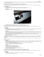
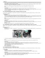
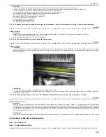
At time of installation, it is often found that the secondary transfer roller of this machine is soiled with yellow toner as shown in the figure; however, this is
the normal condition. The roller is purposefully coated with yellow toner to prevent void from being caused by friction generated when the secondary roller
slides on the ITB belt.
F-15-63
Field Remedy
1. Be sure not to clean the yellow toner applied to the secondary transfer roller.
2. In case the toner is removed accidentally, execute the following service mode to apply yellow toner again: Service Mode > COPIER > Function >
CLEANING > TNR-COAT.
15.3.10.1.5 When Remote Scanner is "online", LED indicator of Start button comes on (i.e., copy operation is enabled)
0017-9810
Color iR C3380G / Color iR C2880G / Color iR C3380i / Color iR C3380 / Color iR C2880i / Color iR C2880 / iR C3480 / iR C3480i / iR C3080i / iR C2550
[ Inspected by Canon Inc. ]
Description
When the screen was switched to the Copy screen while the remote scanner was "online", the message "Online…" was displayed and the LED indicator of
the Start button did not come on; however, when the screen was switched to a pop-up screen such as "Paper Select" or "Special Features" after that, the green
LED indicator of the Start button came on and the copy operation was enabled. According to a specification constraint of this machine, the copy operation is
not enabled while this machine is in "online" state, and therefore the LED indicator shouldn't come on. In order to satisfy this specification constraint, system
software was upgraded to Ver. 50.35.
Field Remedy
When the aforementioned symptom occurs, check the version of system software; if it is earlier than Ver. 50.35, upgrade the software to Ver. 50.35 or later.
15.4 Outline of Electrical Components
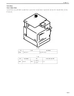
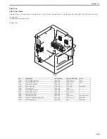
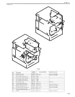
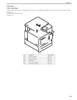
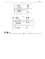
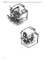
15.4.1 Clutch/Solenoid
15.4.1.1 Clutch/Solenoid Table
0014-0018
Color iR C3380G / Color iR C2880G / Color iR C3380i / Color iR C3380 / Color iR C2880i / Color iR C2880 / iR C3480 / iR C3480i / iR C3080i / iR C2550
Summary of Contents for CiRC2550
Page 2: ......
Page 27: ...Chapter 1 Introduction ...
Page 28: ......
Page 47: ...Chapter 1 1 18 F 1 14 ON OFF ON OFF ...
Page 70: ...Chapter 1 1 41 5 Turn on the main power switch ...
Page 79: ...Chapter 2 Installation ...
Page 80: ......
Page 85: ...Chapter 2 2 3 Not available in some regions ...
Page 134: ...Chapter 3 Basic Operation ...
Page 135: ......
Page 137: ......
Page 143: ...Chapter 4 Main Controller ...
Page 144: ......
Page 152: ...Chapter 4 4 6 F 4 6 CPU HDD ROM access to the program at time of execution ...
Page 171: ...Chapter 5 Original Exposure System ...
Page 172: ......
Page 203: ...Chapter 6 Laser Exposure ...
Page 204: ......
Page 206: ......
Page 220: ...Chapter 7 Image Formation ...
Page 221: ......
Page 277: ...Chapter 8 Pickup Feeding System ...
Page 278: ......
Page 282: ......
Page 336: ...Chapter 9 Fixing System ...
Page 337: ......
Page 339: ......
Page 357: ...Chapter 10 Externals and Controls ...
Page 358: ......
Page 362: ......
Page 366: ...Chapter 10 10 4 F 10 2 F 10 3 FM1 FM2 FM5 FM8 FM11 FM4 FM3 FM6 FM7 FM9 FM10 ...
Page 375: ...Chapter 10 10 13 F 10 10 2 Remove the check mark from SNMP Status Enabled ...
Page 376: ...Chapter 10 10 14 F 10 11 ...
Page 402: ...Chapter 11 MEAP ...
Page 403: ......
Page 405: ......
Page 452: ...Chapter 12 RDS ...
Page 453: ......
Page 455: ......
Page 464: ...Chapter 13 Maintenance and Inspection ...
Page 465: ......
Page 467: ......
Page 469: ...Chapter 13 13 2 F 13 1 8 9 1 2 3 3 5 6 7 10 11 12 13 14 4 ...
Page 474: ...Chapter 14 Standards and Adjustments ...
Page 475: ......
Page 477: ......
Page 485: ......
Page 486: ...Chapter 15 Correcting Faulty Images ...
Page 487: ......
Page 495: ...Chapter 15 15 4 F 15 2 COLOR M 1 COLOR Y C K 0 ...
Page 569: ...Chapter 15 15 78 F 15 82 J102 J107 J103 J108 J101 J109 J106 J112 J115 J113 J114 J104 J105 ...
Page 570: ...Chapter 16 Self Diagnosis ...
Page 571: ......
Page 573: ......
Page 600: ...Chapter 17 Service Mode ...
Page 601: ......
Page 603: ......
Page 712: ...Chapter 18 Upgrading ...
Page 713: ......
Page 715: ......
Page 746: ...Chapter 19 Service Tools ...
Page 747: ......
Page 749: ......
Page 752: ...APPENDIX ...
Page 774: ......


