background image

Routine Cleaning

2-55

2

Ro

utine Main

te

nan

ce

8

Close the feeder cover.

CAUTION


When closing the feeder cover, be careful not to get your fingers caught, 
as this may result in personal injury.

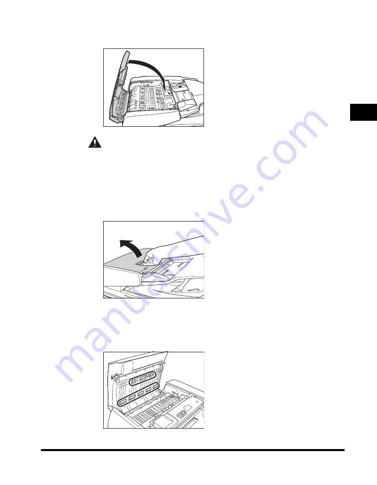
For the imageRUNNER 5050

1

Open the feeder cover.

2

Clean the rollers (a total of eight places) inside the feeder 
cover with a cloth dampened with water. Then, wipe the area 
with a soft, dry cloth.

Summary of Contents for imageRUNNER 5050

Page 1: ...Read this guide first Please read this guide before operating this product After you finish reading this guide store it in a safe place for future reference ENG Support Guide Support Guide...

Page 2: ......

Page 3: ...imageRUNNER 5075 5065 5055 5050 Support Guide 0 Ot...

Page 4: ...u learn the various functions of the machine Tutorial CD CD ROM Precautions for Using Your Machine Troubleshooting Specifications Support Guide This Document Basic Operations Reference Guide CD ROM Co...

Page 5: ...ac UFR II Driver Guide CD ROM Fax Driver Installation and Instructions Fax Driver Guide CD ROM Installing MEAP Applications and Using the Login Service MEAP SMS Administrator Guide CD ROM To view the...

Page 6: ...dix Includes the specifications of the main unit and optional equipment and index How This Manual Is Organized Considerable effort has been made to ensure that this manual is free of inaccuracies and...

Page 7: ...opyright xviii Disclaimers xxiii Legal Limitations on the Usage of Your Product and the Use of Images xxiv Important Safety Instructions xxv Installation xxv Power Supply xxvii Handling xxviii Mainten...

Page 8: ...ts 2 16 Feeder 2 17 Replacing the Stamp Cartridge 2 17 Paper Deck AD1 Paper Deck AE1 Optional 2 20 Loading Paper 2 20 Changing the Paper Size for the Paper Deck AE1 2 24 Finisher AD1 Saddle Finisher A...

Page 9: ...Cover of the Finisher AD1 Saddle Finisher AD2 Optional 3 37 Output Delivery Unit of the Finisher AD1 Saddle Finisher AD2 Optional 3 40 Inside the Front Cover of the Saddle Finisher AD2 Optional 3 45...

Page 10: ...nsertion Folding Unit F1 4 11 Document Insertion Unit E1 4 12 Puncher Unit AT1 4 12 Copy Tray L1 4 13 Card Reader C1 4 13 Provide Adequate Installation Space 4 14 Index 4 15 System Management of the i...

Page 11: ...rning concerning operations that may lead to death or injury to persons if not performed correctly To use the machine safely always pay attention to these warnings CAUTION Indicates a caution concerni...

Page 12: ...Super G3 FAX Board UFR II PCL PS Printer Kit Saddle Finisher AD2 and Puncher Unit AT1 Note that functions that cannot be used depending on the model or options are not displayed on the touch panel di...

Page 13: ...strations Used in This Manual Illustrations used in this manual are those displayed when the imageRUNNER 5075 has the following optional equipment attached to it the Saddle Finisher AD2 and Puncher Un...

Page 14: ...various kinds of prints may sometimes have to wait their turn before they can be printed To avoid confusion when reading this manual the terms scanning printing and copying used throughout this manual...

Page 15: ...xiii Printing data scanned from an original followed by finishing options such as stapling Copying...

Page 16: ...accordance with the Operator s Manual may cause harmful interference to radio communications Operation of this equipment in a residential area is likely to cause harmful interference in which case the...

Page 17: ...not produce hazardous laser radiation Since radiation emitted inside the product is completely confined within protective housings and external covers the laser beam cannot escape from the machine dur...

Page 18: ...at promotes energy saving through the use of computers and other office equipment The program backs the development and dissemination of products with functions that effectively reduce energy consumpt...

Page 19: ...ademarks of Microsoft Corporation in the United States and other countries NetWare is a registered trademark of Novell Inc Java and all Java based trademarks and logos are trademarks or registered tra...

Page 20: ...ley by Ralph Campbell Redistribution and use in source and binary forms with or without modification are permitted provided that the following conditions are met 1 Redistributions of source code must...

Page 21: ...rce and binary forms are permitted provided that the above copyright notice and this paragraph are duplicated in all such forms and that any documentation advertising materials and other materials rel...

Page 22: ...and use acknowledge that the software was developed at Cygnus Solutions Cygnus Solutions may not be used to endorse or promote products derived from this software without specific prior written permis...

Page 23: ...ing terms and conditions The Apache Software License Version 1 1 Copyright c 2000 The Apache Software Foundation All rights reserved Redistribution and use in source and binary forms with or without m...

Page 24: ...e Software Foundation THIS SOFTWARE IS PROVIDED AS IS AND ANY EXPRESSED OR IMPLIED WARRANTIES INCLUDING BUT NOT LIMITED TO THE IMPLIED WARRANTIES OF MERCHANTABILITY AND FITNESS FOR A PARTICULAR PURPOS...

Page 25: ...NSIDE THIS PRODUCT CONTAIN MERCURY AND MUST BE RECYCLED OR DISPOSED OF ACCORDING TO LOCAL STATE OR FEDERAL LAWS For CA USA only Included battery contains Perchlorate Material special handling may appl...

Page 26: ...print or otherwise reproduce any particular document and or of the use of the images scanned printed or otherwise reproduced you should consult in advance with your legal advisor for guidance Paper Mo...

Page 27: ...e following items on the machine If these items come into contact with a high voltage area inside the machine it may result in a fire or electrical shock If these items are dropped or spilled inside t...

Page 28: ...n near water faucets or water A location exposed to direct sunlight A location subject to high temperatures A location near open flames Do not remove the machine s leveling feet after the machine has...

Page 29: ...ther than the power cord provided as this may result in a fire or electrical shock As a general rule do not use extension cords Using an extension cord may result in a fire or electrical shock If an e...

Page 30: ...rwise the power cord or interface cable may be damaged resulting in a fire or electrical shock Do not drop paper clips staples or other metal objects inside the machine Also do not spill water liquids...

Page 31: ...as during consecutive holidays Do not place your hands hair clothing etc near the exit and feed rollers Even if the machine is not in operation your hands hair or clothing may get caught in the rolle...

Page 32: ...the laser beam cannot escape from the machine during any phase of user operation Read the following remarks and instructions for safety Never open covers other than those instructed in this manual Do...

Page 33: ...esult in a fire Clean the machine using a slightly dampened cloth with a mild detergent mixed with water Do not use alcohol benzene paint thinner or other flammable substances Check detergent for flam...

Page 34: ...tely consult a physician When loading paper or removing jammed originals or paper take care not to cut your hands on the edges of the originals or paper When removing a used toner cartridge remove the...

Page 35: ...mantle the toner cartridge as dismantling it may cause toner dust to scatter on your skin or clothes Immediately brush the toner off your clothes but do not wash the clothing with hot water which may...

Page 36: ...inspecting the breaker If a malfunction occurs after an inspection contact your local authorized Canon dealer Checking the Breaker 1 Push the test button with the tip of a ball point pen or a similar...

Page 37: ...ver does not switch to the OFF side position repeat step 1 If the breaker lever does not switch to the OFF side position despite carrying out the above procedure two or three times contact your local...

Page 38: ...xxxvi 5 Fill in the check sheet located on the next page to document your periodic inspections of the breaker...

Page 39: ...Breaker on p xxxiv once or twice a month How to Fill in This Check Sheet Fill in the date of inspection and the name of the inspector When the inspection is completed successfully write a check mark u...

Page 40: ...xxxviii...

Page 41: ...Location and Handling 1 2 Installation Precautions 1 2 Handling Precautions 1 6 Backing Up Data 1 9 Parts and Their Functions 1 10 External View 1 10 Internal View 1 12 Feeder Parts and Functions 1 1...

Page 42: ...ling the Machine in the Following Locations Avoid locations subject to temperature and humidity extremes whether low or high For example avoid installing the machine near water faucets hot water heate...

Page 43: ...tion runs especially in poorly ventilated rooms It is recommended that the room be appropriately ventilated sufficient to maintain a comfortable working environment in areas of machine operation Avoid...

Page 44: ...vibrations generated by the machine during printing can adversely affect the operation of such equipment Avoid installing the machine near televisions radios or similar electronic equipment The machin...

Page 45: ...is connected Do not connect the power cord to a multiplug power strip as this may cause a fire or electrical shock The power cord may become damaged if it is often stepped on or if heavy objects are p...

Page 46: ...and temperatures Take adequate precautions when inspecting the inside of the machine Do not carry out any inspections not described in this manual Be careful not to spill liquid or drop any foreign o...

Page 47: ...horized Canon dealer Using the machine in this state may cause a fire or electrical shock Also avoid placing objects around the power plug so that the machine can be disconnected whenever necessary Do...

Page 48: ...y ventilated rooms It is recommended that the room be appropriately ventilated sufficient to maintain a comfortable working environment in areas of machine operation For safety reasons turn OFF the co...

Page 49: ...mporary backing up of your data by delivering data registered in the machine to other client machines For information on the Device Information Delivery Settings mode see Chapter 6 System Manager Sett...

Page 50: ...Reference Guide External View a Feeder Originals placed in the feeder are automatically fed sheet by sheet to the platen glass for scanning You can select to scan originals as two sided documents wit...

Page 51: ...pen this cover when clearing a paper jam inside the main unit See Inside the Upper and Lower Right Covers on p 3 23 g Paper Drawers 3 and 4 Holds up to 550 sheets of paper 20 lb bond 80 g m2 h Paper D...

Page 52: ...t Unit 2 See Main Unit Fixing Unit and Duplexing Unit on p 3 15 d Fixing Unit Unit 1 Pull out the fixing unit to clear a paper jam See Main Unit Fixing Unit and Duplexing Unit on p 3 15 e Duplexing Un...

Page 53: ...h as books or magazines do not press down hard on the feeder If the original output area is blocked originals may get damaged and printing may not be performed correctly Therefore do not place any obj...

Page 54: ...tals on the touch panel display f Stop key Press to stop a job in progress such as a scan copy or fax scanning only job g Start key Press to start an operation h Main Power Indicator Lights when the m...

Page 55: ...chine p Help key Press to display explanations and instructions of modes or functions on the touch panel display q Reset key Press to restore the standard settings of the machine r Touch Panel Display...

Page 56: ...power plug is firmly inserted into the power outlet WARNING Do not connect or disconnect the power cord with wet hands as this may result in electrical shock 2 Press the main power switch to the I si...

Page 57: ...Sign On is not set and an application other than MEAP is selected as the initial function in Common Settings from the Additional Functions screen The Start Up screen is displayed until the machine is...

Page 58: ...Copying and Mail Box Guide and Chapter 9 Customizing Communications Settings in the Sending and Facsimile Guide You can select which functions to display on the Basic Features screen when turning ON t...

Page 59: ...screen is displayed You can press to switch to the Basic Features screen to use the Copy Mail Box etc functions even if the MEAP Start Up screen is still displayed The MEAP Application screen is displ...

Page 60: ...n power OFF if the optional Universal Send Kit is activated or the Super G3 FAX Board is installed and you want to be able to send or receive fax documents Sending or receiving I fax or fax documents...

Page 61: ...the control panel power switch Shutting Down the Machine If there are any jobs currently being processed or a MEAP application is running when the Shutdown mode is activated the machine asks you to c...

Page 62: ...ode in the following cases When the machine is receiving device information When the machine is browsing device information When the machine is importing or exporting data using the Remote UI function...

Page 63: ...en the current job is displayed on the first line and the other jobs are processed in the order in which they were reserved up to seven jobs 3 Confirm the message displayed press Yes If There Are Jobs...

Page 64: ...s on the screen Press Yes CAUTION You can also force the shutdown of the machine omitting the normal job cancellation process by pressing Forced Off If you press Forced Off while data is being process...

Page 65: ...s It may take some time for the machine to completely shut down depending on the application you are using The screen below is displayed when you press Forced Off in any of the following cases When th...

Page 66: ...r and Control Panel Power 1 26 1 Before You Start Using This Machine IMPORTANT The machine may continue to operate during or after the shutdown process Do not unplug the power cord until the device so...

Page 67: ...ecting the Machine to the Network See the Network Quick Start Guide Setting Up the Network See the Network Guide Installing the Printer Driver See the PS Driver Guide PCL Driver Guide UFR II Driver Gu...

Page 68: ...System Settings 1 28 1 Before You Start Using This Machine...

Page 69: ...Paper 2 20 Changing the Paper Size for the Paper Deck AE1 2 24 Finisher AD1 Saddle Finisher AD2 Puncher Unit AT1 Optional 2 32 Replacing the Staple Cartridge in the Stapler Unit 2 32 Replacing the St...

Page 70: ...For more information on available paper stock that can be loaded into the paper drawers see Chapter 2 Basic Operations in the Reference Guide Loading Paper If the selected paper runs out or the selec...

Page 71: ...a thermal transfer printer Do not print on the reverse side of this paper either Fan the stack of paper well before loading it and align the edges of the paper stack on a flat surface Never place pape...

Page 72: ...Paper Drawers 2 4 2 Routine Maintenance 1 Press and release the button on the paper drawer in which you want to load paper 2 Grip the handle and pull out the paper drawer until it stops...

Page 73: ...re not to cut your hands on the edges of the paper IMPORTANT Rewrap any remaining paper in its original package and store it in a dry place away from direct sunlight NOTE For high quality printouts us...

Page 74: ...hange the size plate to match the paper size being loaded See Adjusting a Paper Drawer to Hold a Different Paper Size on p 2 8 When loading paper into the paper drawer make sure that the paper size se...

Page 75: ...er the side facing down is the one printed on If problems occur such as poor print quality or paper jams try turning the paper stack over and reload it For more information on the print direction of p...

Page 76: ...nel display The machine automatically restarts and produces the remaining copies or prints Adjusting a Paper Drawer to Hold a Different Paper Size If you want to load a different paper size into Paper...

Page 77: ...n 3 Squeeze the lever on the front guide as shown below Without releasing the lever slide the front guide to align it with the mark for the desired paper size IMPORTANT If the left and front guides ar...

Page 78: ...s on the edges of the paper 5 Change the paper drawer s size plate to match the new paper size 6 Gently push the paper drawer back into the machine until it clicks into place in the closed position CA...

Page 79: ...load tab paper The optional Tab Feeding Attachment A1 includes the one touch supports tab paperweight bar and underlay sheet IMPORTANT Tab paper is available in LTR size only NOTE When tab paper is l...

Page 80: ...er on the front guide as shown below Without releasing the lever slide the front guide to align it with the mark for tab paper LTR IMPORTANT If the left and front guides are not adjusted properly for...

Page 81: ...ce down with the tabs facing left as shown in the illustration below Even out the edges of the paper stack Load the paper stack against the right wall of the paper drawer IMPORTANT Paper which has bee...

Page 82: ...without releasing the lever slide the front guide to align it with the tab paper 8 Remove the tab paperweight bar from its holder and place it as shown below to hold the tab paper in place NOTE When y...

Page 83: ...njury IMPORTANT Never place paper or any other items in the open part of the paper drawer next to the paper stack Doing so may cause a paper jam NOTE When you load tab paper make sure to store the tab...

Page 84: ...upports This section describes how to attach the one touch supports for storing the tab paperweight bar 1 Insert the two one touch supports into the paper drawer as shown below 2 Press down on the top...

Page 85: ...to allow toner to come into contact with your hands or clothing If toner gets onto your hands or clothing wash it off immediately with cold water Replacing the Stamp Cartridge 1 Open the feeder cover...

Page 86: ...he new stamp cartridge until it clicks into place using the provided tweezers IMPORTANT Make sure that the stamp cartridge is not protruding from the surface Insert the stamp cartridge properly or pap...

Page 87: ...re using the imageRUNNER 5075 5065 5055 first close the cover with the blue tab and then close the cover with the green tab to close the inner cover CAUTION When closing the covers be careful not to g...

Page 88: ...s case press the control panel power switch to reactivate the machine and then press the open button on the paper deck NOTE The following paper sizes can be loaded into the paper decks Paper Deck AD1...

Page 89: ...ade after you load the correct paper If you select another paper source the remaining prints are made after you press OK 1 Press the open button to open the paper deck The inside lifter automatically...

Page 90: ...using a thermal transfer printer Do not print on the reverse side of this paper either NOTE For high quality printouts use paper recommended by Canon Before loading paper always fan the sheets several...

Page 91: ...paper about which side of the paper to load follow those instructions When paper is loaded in the paper deck the side facing up is the one printed on If problems occur such as poor print quality or p...

Page 92: ...erence Guide 1 Register the desired paper size for the paper deck in Register Sizes for Side Paper Deck in Common Settings from the Additional Functions screen For instructions on registering the pape...

Page 93: ...2 25 2 Routine Maintenance 3 Remove all of the loaded paper and the paper size sheet 4 Remove the white screw on the top of the back size switch plate A by turning it counterclockwise 5 Remove size s...

Page 94: ...move the white screw on the back size switch plate B 7 Remove the back size switch plate B 8 Align the back size switch plate B with the marks for the desired paper size Back Size Switch Plate B 11x17...

Page 95: ...the paper deck with the white screw by turning it clockwise 10 Insert and align size switch plate A with the marks for the desired paper size 11 Fix the size switch plate A with the white screw by tu...

Page 96: ...ded in the paper deck the correct paper size may not appear on the touch panel display Adjust the back size switch plates correctly to avoid causing a paper jam dirty prints or make the inside of the...

Page 97: ...e white screw by turning it clockwise IMPORTANT If the front size switch plate is not adjusted properly for the paper size loaded in the paper deck the correct paper size may not appear on the touch p...

Page 98: ...the guide on the paper deck s left wall 17 Load the paper stack into the paper deck CAUTION When loading paper take care not to cut your hands on the edges of the paper IMPORTANT Paper which has been...

Page 99: ...follow those instructions When paper is loaded in the paper deck the side facing up is the one printed on If problems occur such as poor print quality or paper jams try turning the paper stack over an...

Page 100: ...r Unit AT1 Replacing the Staple Cartridge in the Stapler Unit When the optional Finisher AD1 or Saddle Finisher AD2 is almost out of staples and the staple cartridge in the stapler unit must be replac...

Page 101: ...e front cover of the finisher 2 Lift and pull out the staple case from the stapler unit holding it by its green tab 3 Place the staple case as shown below press the area indicated by PUSH and then pul...

Page 102: ...tended for use with this machine Do not remove the seal that holds the staples together before you place the staple cartridge into the staple case NOTE Only one staple cartridge can be inserted at a t...

Page 103: ...ont cover of the finisher CAUTION When closing the front cover of the finisher be careful not to get your fingers caught as this may result in personal injury NOTE If there are no staples ready for st...

Page 104: ...e touch panel display Follow the procedure described below to replace the staple cartridge Use only staple cartridges intended for use with this machine IMPORTANT This procedure is necessary only if t...

Page 105: ...le stitcher unit by its handle and pull it out of the finisher until it stops 3 Pull the stapler unit of the saddle stitcher unit towards you and then push it up 4 Pull out the empty staple cartridge...

Page 106: ...Insert the new staple cartridge NOTE Only one front and rear staple cartridge can be inserted at a time 6 Pull the stapler unit of the saddle stitcher unit towards you and then push it down into its o...

Page 107: ...have replaced the staple cartridge be sure to manually reposition the staples in the saddle stitcher unit See Chapter 4 Customizing Settings in the Reference Guide Removing Punch Waste When the punch...

Page 108: ...r AD2 Puncher Unit AT1 Optional 2 40 2 Routine Maintenance 1 Open the front cover of the punch waste tray 2 Pull out the punch waste tray 3 Discard the punch waste NOTE Make sure that the punch waste...

Page 109: ...to its original position NOTE If the punch waste tray is not securely in place you cannot make prints in the Hole Punch mode 5 Close the front cover of the punch waste tray CAUTION When closing the f...

Page 110: ...E1 Optional This section describes how to load paper into the insertion unit Loading Paper This section describes the procedure for feeding sheets using the optional Document Insertion Folding Unit F1...

Page 111: ...ke copies or prints on paper that is loaded in the document insertion unit You can load 11 x 17 LGL LTR LTRR or EXEC paper into the tray of the document insertion unit A maximum of 100 sheets of paper...

Page 112: ...correctly it could adversely affect the quality of the image Moreover the fixing unit may become dirty and require a service repair or the paper could jam NOTE For more information on paper types see...

Page 113: ...er be made a screen with instructions on how to replace the toner cartridge like the one shown below appears on the touch panel display Follow the instructions on the touch panel display and the proce...

Page 114: ...cartridges intended for use with this machine Do not replace toner cartridges until the message prompting you to do so appears NOTE You can replace a toner cartridge during the machine is printing Whe...

Page 115: ...r the locking lever all the way to the Unlock position Otherwise you may not be able to remove the toner cartridge 3 Remove the toner cartridge supporting it with both hands CAUTION Do not touch the t...

Page 116: ...ne as shown below IMPORTANT Align the ribbed end of the toner cartridge with the toner supply port as shown in the illustration above Only use toner cartridges intended for use in this machine Insert...

Page 117: ...ers caught as this may result in personal injury IMPORTANT Make sure to return the locking lever all the way to the Lock position Otherwise the toner cartridge will not be inserted properly 6 Close th...

Page 118: ...observe these steps may result in a fire or electrical shock Do not use alcohol benzene paint thinner or other solvents for cleaning Doing so may result in damage to the plastic parts Disconnect the p...

Page 119: ...the platen glass or the underside of the feeder is dirty the original may not be scanned clearly or the size of the original may be detected incorrectly 1 Clean the platen glass and the underside of...

Page 120: ...feeder s rollers CAUTION Do not dampen the cloth too much as this may damage the original or break the machine IMPORTANT Spin the rollers while cleaning them For the imageRUNNER 5075 5065 5055 1 Open...

Page 121: ...as shown below with a cloth dampened with water Then wipe the area with a soft dry cloth 4 Open the inner cover holding it by its tab 5 Clean the rollers a total of four places inside the inner cover...

Page 122: ...al of four places on the underside of the inner cover with a cloth dampened with water Then wipe the area with a soft dry cloth 7 Close the inner cover CAUTION When closing the inner cover be careful...

Page 123: ...the feeder cover be careful not to get your fingers caught as this may result in personal injury For the imageRUNNER 5050 1 Open the feeder cover 2 Clean the rollers a total of eight places inside th...

Page 124: ...as shown below with a cloth dampened with water Then wipe the area with a soft dry cloth 4 Open the inner cover holding it by its tab 5 Clean the rollers a total of nine places inside the inner cover...

Page 125: ...al of four places on the underside of the inner cover with a cloth dampened with water Then wipe the area with a soft dry cloth 7 Close the inner cover CAUTION When closing the inner cover be careful...

Page 126: ...r appear dirty after scanning them through the feeder clean the rollers of the feeder NOTE It takes approximately 15 seconds to clean the feeder 1 Press Additional Functions Adjustment Cleaning Feeder...

Page 127: ...ent Cleaning Wire Cleaning 2 Press Start When cleaning is complete try printing again Drum Cleaning If you use the machine immediately after installation or if the machine is not used for a long perio...

Page 128: ...ks appear on the output In this case clean the original scanning area of the feeder by following the directions displayed in Original Scanning Area Cleaning Method in Adjustment Cleaning from the Addi...

Page 129: ...t to the rubber roller with a well wrung out damp cloth Then wipe the area with a soft dry cloth 4 Pull the lever on the top part of the feeder to open the cover of the feeder s original scanning area...

Page 130: ...Routine Cleaning 2 62 2 Routine Maintenance 6 Fold the cleaning cloth in two as shown below 7 Attach the cleaning cloth to the original scanning area cleaning tool 8 Open the inner cover...

Page 131: ...the inner cover CAUTION When closing the inner cover be careful not to get your fingers caught as this may result in personal injury 11 Remove the cleaning cloth from the original scanning area clean...

Page 132: ...rea cover CAUTION When closing the feeder s original scanning area cover be careful not to get your fingers caught as this may result in personal injury 13 Close the feeder CAUTION When closing the fe...

Page 133: ...ift the feeder 2 Clean the feeder s scanning area with a cloth dampened with water Then wipe the area with a soft dry cloth 3 Clean the part located next to the rubber roller with a cloth dampened wit...

Page 134: ...Routine Cleaning 2 66 2 Routine Maintenance 4 Close the feeder CAUTION When closing the feeder be careful not to get your fingers caught as this may result in personal injury...

Page 135: ...nded for this machine tracing paper labels and other types of paper stock are available For more information contact your local authorized Canon dealer CAUTION Do not store paper in places exposed to...

Page 136: ...lames as this may cause the toner to ignite resulting in burns or a fire CAUTION Keep toner and other consumables out of the reach of small children If these items are ingested consult a physician imm...

Page 137: ...d Toner Parts and Supplies specifically for use in this machine For optimal print quality and for optimal machine performance and productivity we recommend that you use Genuine Canon Toner Parts and S...

Page 138: ...Consumables 2 70 2 Routine Maintenance...

Page 139: ...he Finisher AD1 Saddle Finisher AD2 Optional 3 37 Output Delivery Unit of the Finisher AD1 Saddle Finisher AD2 Optional 3 40 Inside the Front Cover of the Saddle Finisher AD2 Optional 3 45 Saddle Stit...

Page 140: ...3 2 3 Troubleshooting 3 Troubleshooting Setting the Limited Functions Mode from the Service Call Message Screen 3 100 When the Power Does Not Turn ON 3 103...

Page 141: ...ere are torn pieces of paper left inside the machine Pulling jammed paper out of the machine by force may leave parts of the paper torn inside leading to frequent paper jams If paper tears while you a...

Page 142: ...on of the Paper Jam The location of the paper jam is indicated by a red circle in the upper right corner of the screen If you press Recover Later you can continue operations such as setting modes and...

Page 143: ...ur hands or clothing If they become dirty wash them immediately with cold water Washing them with warm water will set the toner and make it impossible to remove the toner stains When removing paper wh...

Page 144: ...after the power is turned back ON Clear paper jams without turning the power OFF NOTE Some areas that are shown to have paper jams may not actually have paper jams However always check all locations...

Page 145: ...ooting 2 If a paper jam occurs inside an optional unit see the instructions on the following pages Paper Deck AD1 See Paper Deck AD1 Paper Deck AE1 Optional on p 3 33 Paper Deck AE1 See Paper Deck AD1...

Page 146: ...of the Finisher AD1 Saddle Finisher AD2 Optional on p 3 40 Saddle Finisher AD2 See Inside the Top Cover of the Finisher AD1 Saddle Finisher AD2 Optional on p 3 37 See Output Delivery Unit of the Finis...

Page 147: ...Optional on p 3 53 See Inside the Insertion Unit Optional on p 3 58 See Document Insertion Folding Unit F1 Optional on p 3 62 Document Insertion Unit E1 See Insertion Unit Optional on p 3 53 See Insid...

Page 148: ...panel display Once you have removed all of the jammed paper in locations other than the feeder printing or copying resumes If there is paper that still needs to be removed a screen indicating how to...

Page 149: ...d paper WARNING There are some areas inside the machine which are subject to high voltages When removing jammed paper or when inspecting the inside of the machine do not allow necklaces bracelets or o...

Page 150: ...any jammed originals 3 Open the inner cover holding it by its tab 4 Turn the feed dial and remove any jammed originals imageRUNNER 5050 imageRUNNER 5075 5065 5055 imageRUNNER 5050 imageRUNNER 5075 50...

Page 151: ...careful not to get your fingers caught as this may result in personal injury 6 Close the feeder cover CAUTION When closing the feeder cover be careful not to get your fingers caught as this may result...

Page 152: ...may result in personal injury 9 Follow the instructions on the touch panel display NOTE The screen indicating the location of the paper jam repeatedly appears on the touch panel display until the pape...

Page 153: ...e paper jam and follow the procedure described below and the procedure that appears on the touch panel display to remove the jammed paper CAUTION The fixing unit and its surroundings inside the machin...

Page 154: ...he arrow counterclockwise 3 Move the green lever in the direction of the arrow counterclockwise 4 Grip the green lever and pull out the fixing unit Unit 1 and duplexing unit Unit 2 NOTE The fixing uni...

Page 155: ...ION The fixing unit and its surroundings are subject to high temperatures When removing jammed paper take care not to touch anything in this area except the jammed paper and the green knob 6 Open the...

Page 156: ...reful not to get your fingers caught as this may result in personal injury 9 Gently push only the fixing unit back into the machine CAUTION When pushing the fixing unit back into the machine be carefu...

Page 157: ...eft cover of the duplexing unit and remove any jammed paper as shown in the illustration 13 Lift up the top cover of the duplexing unit and remove any jammed paper and then close the top cover CAUTION...

Page 158: ...ush the duplexing unit back into the machine CAUTION When pushing the duplexing unit back into the machine be careful not to get your fingers caught as this may result in personal injury 16 Close the...

Page 159: ...he stack bypass a screen similar to the one shown below appears on the touch panel display Check the location of the paper jam and follow the procedure described below and the procedure that appears o...

Page 160: ...k bypass inside the upper right cover of the main unit 4 Gently close the upper right cover of the main unit until it clicks into place in the closed position If the optional Paper Deck AD1 or Paper D...

Page 161: ...tedly appears on the touch panel display until the paper jam is entirely cleared For more information see Screens Indicating the Locations of Paper Jams on p 3 4 Inside the Upper and Lower Right Cover...

Page 162: ...ttached to the main unit press the release button and move the paper deck away from the main unit before proceeding with this procedure For more information see Chapter 3 Optional Equipment in the Ref...

Page 163: ...l injury 4 Open the lower right cover of the main unit 5 Remove any jammed paper 6 Gently close the lower right cover of the main unit until it clicks into place in the closed position If the optional...

Page 164: ...panel display until the paper jam is entirely cleared For more information see Screens Indicating the Locations of Paper Jams on p 3 4 Paper Drawer 1 If a paper jam occurs inside Paper Drawer 1 a scr...

Page 165: ...ove the paper deck away from the main unit before proceeding with this procedure For more information see Chapter 3 Optional Equipment in the Reference Guide 2 Grip the handle and pull out the paper d...

Page 166: ...to its original position be careful not to get your fingers caught as this may result in personal injury 5 Follow the instructions on the touch panel display NOTE The screen indicating the location o...

Page 167: ...paper jam and follow the procedure described below and the procedure that appears on the touch panel display to remove the jammed paper 1 Press and release the button on Paper Drawer 2 2 Grip the han...

Page 168: ...paper drawer to its original position be careful not to get your fingers caught as this may result in personal injury 5 Follow the instructions on the touch panel display NOTE The screen indicating t...

Page 169: ...ow appears on the touch panel display Check the location of the paper jam and follow the procedure described below and the procedure that appears on the touch panel display to remove the jammed paper...

Page 170: ...e paper drawer to its original position be careful not to get your fingers caught as this may result in personal injury 5 Follow the instructions on the touch panel display NOTE The screen indicating...

Page 171: ...s inside the machine which are subject to high voltages When removing jammed paper or when inspecting the inside of the machine do not allow necklaces bracelets or other metal objects to touch the ins...

Page 172: ...1 Press the release button and move the paper deck away from the main unit 2 Remove any jammed paper from the feeding area Paper can also be jammed in the feeding slot on the side of the main unit Rem...

Page 173: ...main unit be careful not to get your fingers caught as this may result in personal injury 4 Press the open button to open the paper deck The inside lifter descends automatically IMPORTANT If the machi...

Page 174: ...e paper deck be careful not to get your fingers caught as this may result in personal injury 7 Follow the instructions on the touch panel display NOTE The screen indicating the location of the paper j...

Page 175: ...n removing jammed paper take care not to cut your hands on the edges of the paper When removing paper which has become jammed inside the machine take care not to cut your hands or injure yourself on t...

Page 176: ...r open the front cover of the punch waste tray and then open the top cover of the puncher unit to remove any jammed paper If the optional Document Insertion Folding Unit F1 or Document Insertion Unit...

Page 177: ...e top cover of the finisher be careful not to get your fingers caught as this may result in personal injury 5 Close the front cover of the finisher CAUTION When closing the front cover of the finisher...

Page 178: ...When removing jammed paper take care not to cut your hands on the edges of the paper When removing paper which has become jammed inside the machine take care not to cut your hands or injure yourself...

Page 179: ...g to be stapled Printing and stapling resume after you clear the paper jam 2 Open the front cover of the finisher If the optional Puncher Unit AT1 is attached to the main unit and paper has jammed bet...

Page 180: ...leshooting 3 Open the top cover of the finisher 4 Open the delivery guide 5 Remove any jammed paper If the jammed paper does not come out easily open the entrance guide and then remove the jammed pape...

Page 181: ...ptional Puncher Unit AT1 is attached to the main unit close the top cover of the puncher unit and the front cover of the punch waste tray after removing the jammed paper If the optional Document Inser...

Page 182: ...t as this may result in personal injury 9 Follow the instructions on the touch panel display NOTE The screen indicating the location of the paper jam repeatedly appears on the touch panel display unti...

Page 183: ...paper take care not to cut your hands on the edges of the paper When removing paper which has become jammed inside the machine take care not to cut your hands or injure yourself on the inside of the...

Page 184: ...jammed between the puncher unit and the finisher open the front cover of the punch waste tray and then open the top cover of the puncher unit to remove any jammed paper If the optional Document Insert...

Page 185: ...al position when released CAUTION When releasing the upper delivery guide be careful not to get your fingers caught as this may result in personal injury 4 Tilt the lower delivery guide to the right a...

Page 186: ...inisher If the optional Puncher Unit AT1 is attached to the main unit close the top cover of the puncher unit and the front cover of the punch waste tray after removing the jammed paper If the optiona...

Page 187: ...repeatedly appears on the touch panel display until the paper jam is entirely cleared For more information see Screens Indicating the Locations of Paper Jams on p 3 4 Saddle Stitcher Unit Optional If...

Page 188: ...If you cannot remove the paper contact your local authorized Canon dealer When removing paper which has become jammed inside the machine take care not to allow the toner on the jammed paper to come in...

Page 189: ...2 Turn the small knob on the right in the direction of the arrow counterclockwise 3 While pushing in the larger knob on the left turn it in the direction of the arrow clockwise 4 Remove any jammed pap...

Page 190: ...ower delivery guide to the right until it stops and then tilt the lower delivery guide to the right 6 Return the lower delivery guide to its original position CAUTION When closing the delivery guide b...

Page 191: ...nal If a paper jam occurs inside the insertion unit of the optional Document Insertion Folding Unit F1 or optional Document Insertion Unit E1 a screen similar to the one shown below appears on the tou...

Page 192: ...oner stains When removing paper which has become jammed inside the machine remove the jammed paper gently to prevent the toner on the paper from scattering and getting into your eyes or mouth If the t...

Page 193: ...3 Remove any jammed paper 4 Close the top cover of the document insertion folding unit document insertion unit CAUTION When closing the top cover of the document insertion folding unit document insert...

Page 194: ...g Paper Jams 3 56 3 Troubleshooting 5 Open the front cover of the document insertion folding unit document insertion unit 6 Open the insertion unit 7 Open the output delivery unit and remove the jamme...

Page 195: ...output delivery unit 9 Close the insertion unit CAUTION When closing the insertion unit be careful not to get your fingers caught as this may result in personal injury 10 Close the front cover of the...

Page 196: ...ouch the inside of the machine as this may result in burns or electrical shock CAUTION When removing jammed paper take care not to cut your hands on the edges of the paper When removing paper which ha...

Page 197: ...or staple jams prints may still be output if other optional units are operating normally and are not involved in the paper or staple jam removal procedure NOTE This procedure is only required when an...

Page 198: ...ubleshooting 3 Remove any jammed paper 4 Close the upper delivery guide CAUTION When closing the upper delivery guide be careful not to get your fingers caught as this may result in personal injury 5...

Page 199: ...ammed paper 7 Close the lower delivery guide CAUTION When closing the lower delivery guide be careful not to get your fingers caught as this may result in personal injury 8 Close the front cover of th...

Page 200: ...ne as this may result in burns or electrical shock CAUTION When removing jammed paper take care not to cut your hands on the edges of the paper When removing paper which has become jammed inside the m...

Page 201: ...punch waste or clear paper or staple jams prints may still be output if other optional units are operating normally and are not involved in the paper or staple jam removal procedure NOTE This procedur...

Page 202: ...Clearing Paper Jams 3 64 3 Troubleshooting 3 Pull out the document insertion folding unit 4 Push out any jammed paper toward the exit slot 5 Remove the jammed paper...

Page 203: ...Clearing Paper Jams 3 65 3 Troubleshooting 6 Open the left guide 7 Remove any jammed paper When there is a paper jam in the inside guide When there is a paper jam in the outside guide...

Page 204: ...ms 3 66 3 Troubleshooting 8 Open the right guide 9 Remove any jammed paper 10 Close the right guide CAUTION When closing the right guide be careful not to get your fingers caught as this may result in...

Page 205: ...reful not to get your fingers caught as this may result in personal injury 12 Return the document insertion folding unit to its original position CAUTION When returning the document insertion folding...

Page 206: ...ivery guide be careful not to get your fingers caught as this may result in personal injury 14 Close the front cover of the document insertion folding unit CAUTION When closing the front cover of the...

Page 207: ...similar to the one shown below appears on the touch panel display Check the location of the paper jam and follow the procedure described below and the procedure that appears on the touch panel display...

Page 208: ...n unit open the insertion unit proceed to step 3 4 Remove any jammed paper 5 Close the top cover of the puncher unit If the optional Document Insertion Folding Unit F1 or Document Insertion Unit E1 is...

Page 209: ...the location of the paper jam repeatedly appears on the touch panel display until the paper jam is entirely cleared For more information see Screens Indicating the Locations of Paper Jams on p 3 4 Co...

Page 210: ...the toner on the jammed paper to come into contact with your hands or clothing as this will dirty your hands or clothing If they become dirty wash them immediately with cold water Washing them with wa...

Page 211: ...f the arrow counterclockwise 3 Move the green lever in the direction of the arrow counterclockwise 4 Grip the green lever and pull out the fixing unit Unit 1 and duplexing unit Unit 2 NOTE The fixing...

Page 212: ...its surroundings are subject to high temperatures When removing jammed paper take care not to touch anything in this area except the jammed paper and the green knob 6 Gently push the fixing unit and d...

Page 213: ...f the main unit be careful not to get your fingers caught as this may result in personal injury 9 Follow the instructions on the touch panel display NOTE The screen indicating the location of the pape...

Page 214: ...or optional Saddle Finisher AD2 a screen similar to the one shown below appears on the touch panel display Check the location of the staple jam and follow the procedure described below and the procedu...

Page 215: ...e Jams 3 77 3 Troubleshooting 2 Lift and pull out the staple case from the stapler unit holding it by its green tab 3 Push down the tab on the staple case 4 Remove all of the staples that slide from t...

Page 216: ...Close the front cover of the finisher CAUTION When closing the front cover of the finisher be careful not to get your fingers caught as this may result in personal injury NOTE If there are no staples...

Page 217: ...and follow the procedure described below and the procedure that appears on the touch panel display to remove any jammed staples IMPORTANT If necessary make sure to remove all of the paper in the Bookl...

Page 218: ...d pull it out of the finisher until it stops 3 Pull the stapler unit of the saddle stitcher unit towards you and then push it up 4 Pull out the staple cartridge containing the jammed staples holding i...

Page 219: ...Jams 3 81 3 Troubleshooting 5 On the staple case push down Part A and push up Part B 6 Remove any jammed staples and return Part B to its original position 7 Return the staple cartridge to its origina...

Page 220: ...ds you and then push it down into its original position 9 Gently push the saddle stitcher unit back into its original position 10 Close the front cover of the finisher CAUTION When closing the front c...

Page 221: ...taple Jams 3 83 3 Troubleshooting IMPORTANT When you have cleared the staple jam be sure to manually reposition the staples in the saddle stitcher unit See Chapter 4 Customizing Settings in the Refere...

Page 222: ...appear on the touch panel display at the following times When scanning or printing cannot be performed because of an operational error When you need to make a decision or take some action during scann...

Page 223: ...tart Return page 1 to the top and then press the Start key Data for the scanned original has exceeded limits on the size that can be handled by this machine Automatically adjust settings and try again...

Page 224: ...mode requires that the original be placed on the platen glass but there is no original on the platen glass Remedy Place the original on the platen glass Remove the original from the platen glass Cause...

Page 225: ...sults column on the Send Report See Chapter 12 Printing Communication Reports in the Sending and Facsimile Guide Perform the necessary procedures according to the error code 001 Cause 1 Differently si...

Page 226: ...rtment ID or password using numeric keys on the control panel and try again Cause 2 The Department ID or password was changed while the machine was processing a job Remedy Change the Department ID and...

Page 227: ...749 Cause You could not execute the job because a service call message is being displayed Remedy Turn the main power OFF wait for 10 or more seconds and then turn the main power back ON If the machine...

Page 228: ...and password are registered Cause 2 Reserved or current print jobs cannot be performed in the remote copy printer because the Department ID and password have been deleted or the password has been cha...

Page 229: ...than 2 000 documents in the specified inbox Remedy If there are a large number of documents delete the unnecessary ones from the specified inbox See Chapter 2 Introduction to the Mail Box Functions in...

Page 230: ...uments exceeded the maximum limit that can be reserved at a time Remedy Print or erase the secured documents that are stored in the machine and try printing again 854 Cause Device information could no...

Page 231: ...e data Remedy Check the print settings and try printing again Cause 2 An original was not scanned properly or the orientation of the original was incorrect Remedy Check the scan settings and try scann...

Page 232: ...supported was set Remedy Change the print data or print settings and try printing again Cause 3 Image data or data which is not guaranteed to be compatible was printed Remedy Change the print data or...

Page 233: ...ions In addition each function is guaranteed to be able to store the following number of pages For example the Copy function can store up to 20 100 pages of scanned images 100 20 000 20 100 pages appr...

Page 234: ...ancel or Another Function Yes The pages scanned into memory are printed When printing is complete scan the remaining originals No The pages scanned into memory are not printed Another Function Select...

Page 235: ...cel The current job is canceled and the display returns to the Basic Features screen Scan the job again when the current job is complete Another Function Select to use another function that is not bei...

Page 236: ...appears follow the procedure described below WARNING Do not connect or disconnect the power cord with wet hands as this may result in electrical shock CAUTION Always grasp the power plug when disconn...

Page 237: ...main power switch back ON 3 If the machine still does not operate normally follow the procedure below and then contact your local authorized Canon dealer Turn OFF the main power switch Disconnect the...

Page 238: ...er after the Limited Functions Mode is deactivated the Service Call Message screen may appear again unless the cause of the malfunction is removed IMPORTANT If you turn OFF the main power switch when...

Page 239: ...ess Yes A message prompting you to press Shutdown and to turn the main power switch OFF and ON appears 3 Press Shutdown to turn the main power switch OFF 4 Wait at least 10 seconds before turning the...

Page 240: ...Service Call Message 3 102 3 Troubleshooting The machine starts up in the Limited Functions Mode...

Page 241: ...turned ON always check that the breaker is not in the OFF position If the breaker is in the OFF position contact your local authorized Canon dealer without turning the breaker back ON WARNING If the...

Page 242: ...When the Power Does Not Turn ON 3 104 3 Troubleshooting...

Page 243: ...Document Insertion Folding Unit F1 4 11 Document Insertion Unit E1 4 12 Puncher Unit AT1 4 12 Copy Tray L1 4 13 Card Reader C1 4 13 Provide Adequate Installation Space 4 14 Index 4 15 System Manageme...

Page 244: ...lb index 91 to 200 g m2 Paper Drawers 3 and 4 Paper Weight 17 lb bond to 110 lb index 64 to 200 g m2 Paper Type Plain Recycled Color Pre punched Bond Letterhead Heavy 24 lb bond to 110 lb index 91 to...

Page 245: ...0 Approximately 8 seconds Activation time may vary depending on the environment and conditions under which the machine is being used First Copy Time imageRUNNER 5075 3 1 seconds when the original is p...

Page 246: ...m2 Paper Drawers 3 and 4 550 sheets x 2 cassettes 20 lb bond 80 g m2 Stack Bypass 50 sheets 20 lb bond 80 g m2 Multiple Copies 1 to 9 999 sheets Power Source 120V AC 60 Hz 20 A Maximum Power Consumpti...

Page 247: ...Consumption From the main unit 123 W Dimensions H x W x D Weight 6 1 2 x 24 1 4 x 22 1 8 166 2 mm x 615 3 mm x 560 3 mm Approximately 44 5 lb 20 2 kg Item Specification Original Feeding Mechanism Auto...

Page 248: ...e Consumption From the main unit Approximately 62 W Dimensions H x W x D Weight 22 5 8 x 23 1 2 x 24 1 2 574 5 mm x 598 mm x 621 mm Approximately 99 4 lb 45 1 kg Installation Space W x D 66 1 4 x 29 1...

Page 249: ...7 LGL LTRR 650 sheets or 3 3 4 96 mm in height Tray C LTR EXEC 1 700 sheets or 9 5 8 243 6 mm in height 11 x 17 LGL LTRR 650 sheets or 3 3 4 96 mm in height Staple mode Tray B Tray C LTR EXEC 1 300 sh...

Page 250: ...sheets 20 to 24 lb bond 81 to 90 g m2 2 sheets 24 lb bond to 140 lb index 91 to 256 g m2 Corner Staple mode 11 x 17 LGL LTR LTRR EXEC Double Staple mode 11 x 17 LGL LTR LTRR EXEC Power Source Maximum...

Page 251: ...Paper Transparency Labels Tab Paper Capacity Per Tray No Collating mode Tray A LTR STMTR EXEC 250 sheets or 1 5 8 41 mm in height 11 x 17 LGL LTRR 125 sheets or 7 8 21 mm in height Tray B LTR STMTR E...

Page 252: ...sheets 25 sets 6 to 10 sheets 15 sets 11 to 15 sheets 10 sets Max Stapling Capacity Available Staple Size LTR EXEC 50 sheets 17 to 20 lb bond 64 to 80 g m2 30 sheets 20 to 24 lb bond 81 to 90 g m2 2...

Page 253: ...pacity 40 sheets or 2 3 8 60 mm in height 20 lb bond 80 g m2 Paper Size Weight Type Capacity of the document insertion unit Size 11 x 17 LGL LTR LTRR EXEC Weight 17 lb bond to 140 lb index 64 to 256 g...

Page 254: ...ay is extended Item Specification Paper Size Weight Type Size 11 x 17 LGL LTR LTRR Weight 17 lb bond to 110 lb index 64 to 200 g m2 Type Plain Recycled Color Heavy 24 lb bond to 110 lb index 91 to 200...

Page 255: ...Tracing Paper Transparency Labels Tab Paper Capacity 250 sheets 20 lb bond 80 g m2 Dimensions H x W x D Weight 7 3 8 x 17 5 8 x 13 3 8 186 mm x 446 mm x 340 mm when the auxiliary tray and wire are ex...

Page 256: ...side of the machine for unrestricted operation The optional Copy Tray L1 is attached The optional Saddle Finisher AD2 Document Insertion Folding Unit F1 Puncher Unit AT1 and Paper Deck AE1 are attache...

Page 257: ...mp Cartridge 2 68 Toner 2 68 Control panel About the control panel 1 10 Control panel power switch 1 14 Parts and their functions 1 14 Power 1 16 1 21 Control panel power switch 1 14 1 16 1 21 Copy Tr...

Page 258: ...the usage of your product and the use of images xxiv Trademarks xvii Loading paper Document Insertion Folding Unit F1 2 42 Document Insertion Unit E1 2 42 Paper Deck AD1 2 20 Paper Deck AE1 2 20 Pape...

Page 259: ...supply xxvii 1 5 Printing definition xii Processing Data indicator 1 14 Puncher Unit AT1 Clearing paper jams 3 69 Removing punch waste 2 39 Specifications 4 12 R Reset key 1 15 S Saddle Finisher AD2...

Page 260: ...this manual ix T Test button 1 12 Toner cartridge About the toner cartridge 2 68 Replacing 2 45 Trademarks xvii Troubleshooting Clearing paper jams 3 4 Clearing staple jams 3 76 Error messages 3 84 M...

Page 261: ...d by other users The operations which can be performed in the System Management mode are Managing documents in an inbox Managing Mail Box Settings Entering the System Management Mode IMPORTANT If you...

Page 262: ...assword using numeric keys Press Dept ID enter the System Manager ID Press Password enter the System Password Press Log In Out The System Management mode is enabled If Department ID Management Is Not...

Page 263: ...stem Manager ID enter the System Manager ID Press System Password enter the System Password Press Log In Out The System Management mode is enabled NOTE Make sure to enter the System Manager ID and Sys...

Page 264: ...Management Mode The System Manager can access documents in inboxes that have been stored by other users For example you can access an inbox whose user has forgotten his her password and erase any unne...

Page 265: ...mple you can initialize an inbox that is not being used or change the name of an inbox You can also reset the password of an inbox if the user has forgotten it 1 Enter the System Management mode NOTE...

Page 266: ...System Management of the imageRUNNER 5075 5065 5055 5050 4 24 4 Appendix...

Page 267: ......

Page 268: ...A10 47807 Krefeld Germany CANON ITALIA S p A Via Milano 8 20097 San Donato Milanese MI Italy CANON ESPA A S A Joaqu n Costa 41 28002 Madrid Spain CANON LATIN AMERICA INC 703 Waterford Way Suite 400 M...

Reviews: