INSTALLATION
MANUAL
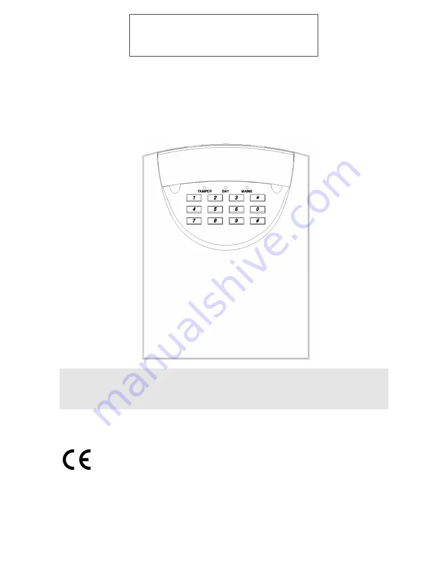
SECURIT 802 CONTROL PANEL
S802
Page 1: ...INSTALLATION MANUAL SECURIT 802 CONTROL PANEL S802 ...
Page 2: ...nal Devices 5 Strobe 5 Keyswitch Connections 5 Aux DC power 5 Mounting Keypads 6 Wiring Keypads 6 Powering Up 6 7 Programming 7 Exit Time 7 Entry Time 7 Bell Duration 8 Night Set Exit Time 8 Home Set Exit Time 8 Circuit Programming 9 Zone Selections 9 Extended Programming 9 Home Set Zone Selection 9 10 Engineer Access Code 10 Engineer Log Review 10 Engineer Test Options 10 Restoring Default Codes ...
Page 3: ...ill incur otherwise the unit will be repaired and returned free of charge PRODUCT DESCRIPTION The Securit 800L hereafter known as the Control Panel is an 8 zone programmable microprocessor control panel using state of the art technology and manufacturing techniques The panel has many advanced features that can only be found in more expensive control panels such as two user codes Chime Fire and Key...
Page 4: ... C to 40 C Humidity 10 to 90 R H non condensing Dimensions 263 mm W 223 mm H 82 mm D Control Panel Weight 2 7 kg Excluding Battery Stand by Battery 1 2 Ah 12 V Rechargeable Lead Acid 2 1 Ah max Maximum Cable Run 100 Metres per run Use For internal use only Factory Defaults User customer Code 1 1234 User customer Code 2 Disabled 0000 Engineer Code 7890 Circuit 1 Entry Circuit Fixed Circuit 2 Alarm ...
Page 5: ...ensure continued safe operation CAUTION Under certain circumstances the transformer metalwork can reach 70 C this is normal and well within prescribed limits Battery connection Maximum battery size 12V 2 1Ah max This panel requires a standby battery to be fitted to provide power in the event of mains failure A valve regulated lead acid battery must be used Detector circuits Connections are provide...
Page 6: ...al sounder and strobe are shown in diagram A Please note sounder trigger is applied negative Negative ring ST Strobe switched negative trigger S Sounder switched negative trigger Sounder hold off strobe positive supply Sounder hold off supply sounder tamper feed negative R Sounder tamper return negative AUX DC Detector power The auxiliary power is provided from connections marked AUX This is to pr...
Page 7: ... for series and parallel examples DIAGRAM C POWERING UP INITIAL POWER UP NOTE The lid should remain off the main control panel so that engineer mode may be used Alternatively entering 7890 can also be used to enter engineer mode If the engineers code is entered and the panel is then left it will set 1 Switch the mains supply on the internal sounder will start This denotes a tamper alarm 2 Enter 1 ...
Page 8: ...d PROGRAMMING Once in engineering mode the day LED will flash You now have the following options available EXIT TIME 3 0 Range 10 90 Seconds Enter 3 0 This has been preset to a factory default of 30 seconds A new time may be programmed by entering one key from the following table Once the desired option is chosen press to confirm The accept tone will sound Enter 1 10 Seconds Led 1 on Enter 2 15 Se...
Page 9: ...n Enter 2 15 Seconds Led 2 on default Enter 3 30 Seconds Led 3 on Enter 4 45 Seconds Led 4 on Enter 5 60 Seconds Led 5 on Enter 6 90 Seconds Led 6 on NOTE The exit sounder volume can be altered by the control on the PCB marked VOLUME or RV1 Please note this will not apply to keypad bleepers Option Option Results from choosing option no Code Description 0 1 2 3 4 5 6 3 0 Exit Time secs 10 15 30 45 ...
Page 10: ... OPTIONS 7 Range 1 8 Further options are available to increase the versatility of the control panel Enter 7 1 Disables sounder strobe in night set Enter 7 2 Chime Enable See user manual for zone allocation Enter 7 3 Full set door sense setting Enter 7 4 Convert L to ID output Enter 7 5 Allow Manual Isolation of Zone 1 Entry Exit In night set Enter 7 6 Remote Keypad PA Enable Operated by Enter 7 7 ...
Page 11: ...ar a continual tone which denotes you are viewing the last set condition There may be no lights illuminated as there may not have been an alarm during that time Pressing the key will turn off the sounder and show the last unset period By pressing 0 you will show the last ALARM condition that was caused in an UNSET period no matter how long ago that alarm was Pressing will bring the sounder back on...
Page 12: ...and is labelled Memory Default at which point zone 1 light will illuminate 2 Wait a few seconds then re connect the battery and then the mains and then refer to page 6 regarding initial power up The speaker will omit the accept tone and the factory user code defaults will be restored 3 Remove the link at which point zone 1 light will go out GLOSSARY OF TERMS FULL SET This is a setting method norma...
Page 13: ...NG This allows you to have a variable FULL SET EXIT TIME You can program the EXIT time to maximum and when you full set the system the exit time will drop to 8 seconds as soon as the EXIT door has closed thus avoiding the preset exit time FULL SET KEYSWITCH This allows the panel to be set unset and reset via zone 8 This is performed by using a 2 position keyswitch make break across the zone To set...
Page 14: ...NTROL PANEL OR WITH THE INSTALLER IT CAN BE USED TO REFER TO PROGRAMMING DETAILS WHEN NEEDED CONTROL PANEL ST S AUX R SONADE 2000 STROBE B D A T FLASHGUARD XL STROBE SIREN SUPPLY SUPPLY TAMPER OUT STARLIGHT 2000 ST R H H RTN ACTIVEGUARD STB S 12V 12V RIGHT HAND TAMPER ACTIVE GUARD 3 ST SW V V RET SECURIGUARD STROBE S SUPPLY SUPPLY LEFT HAND TAMPER NOVA GUARD 2 T STROBE S 12V 12V R SPIRIT AU1000 ST...
Page 15: ...iring Make sure the devices are wired in series NOT parallel Zone activates during entry Seeing an alarm zone on entry or deviating from entry route Make sure all zones on entry route are programmed with walkthrough Don t deviate Zone activates even in day mode Programmed to PA or FIRE Reprogram the zone to be an alarm zone or similar If you are still experiencing problems then contact our technic...
Page 16: ...oat Industrial Estate Redditch Worcs B98 9HE Tel 01527 68111 Fax 01527 68222 Tech Support 0345 660533 9am 5pm Weekdays UK ONLY email to info cksys co uk website http users powernet co uk cksys 5 051 519 01 Approved BS EN ISO No 9002 1994 Certificate No 0944 ...