15
to keep the Gas valve in the open position. The
fan is kept at ignition speed until the flame is
stabilized. As demand increases the modulation
signal causes the Gas valve to draw more gas.
10. The fan speed will slowly decrease as the
temperature nears the target. The modulation
rate is controlled via a PWM signal. If the heat
demand is sustained without change, the boiler
firing rate will reach a point of steady-state and
the fan will rotate at constant speed.
11. When the heat demand is satisfied or the remote
enable is removed, the burner will shut off and
the fan speed will ramp up to the preset Post-
Purge speed until the Post-Purge timer is
satisfied.
12. The pump continues to circulate until the Post-
Purge time is satisfied.
13. The boiler will then go into Standby as it waits for
the next heat demand or remote enable.
NOTE
:
1. If a flame signal is detected at the end of the Pre-
Purge period, an error will occur.
2. If at the end of the safety period (4 sec) no flame
is detected, the control will go to Post-Purge to
remove the unburned gas. After this, a re-ignition
attempt is started following the same cycle. The
number of re-ignition attempts is limited to 2 after
which a lockout occurs.
3. The burner can only be ON continuously for a
period of 24 hours. After this, the burner is
switched OFF and a restart sequence follows.
4. The Hot Surface Igniter is de-energized at the end
of the ignition period to allow for ionization
detection.
HEAT TRANSFER PROCESS
1. Burner input rate continues to increase until water
temperature reaches the set point temperature.
2. Burner input rate may stabilize at a fixed rate when
demand equals input.
3. Burner input rate will decrease when water
temperate approaches temperature set point.
4.2
FIELD START-UP PROCEDURE
Setting the correct combustion is essential to get the best
performance out of the appliance.
1.
Toggle the main power button to the “ON” position.
2. Make sure the boiler is in
“Standby” condition by
setting the LOCAL/REMOTE switch to REMOTE
and disabling all external demand to the boiler.
3. Unlock the SOLA control by pressing the lock
button on the top right and entering the password
“SOLA”.
4. Open the Diagnostics menu, select manual run
and enter the RPM corresponding with the Ps
pressure written on the label behind the front door
of the Valiant FT Series II.
5. Insert Combustion Analyzer into the Exhaust port
and record the combustion readings. If the
readings do not match table 11 below, the
combustion values will need to be changed.
6. Re-enter the RPM corresponding with the low fire
Ps pressure and record the Combustion values
using the Combustion Analyzer.
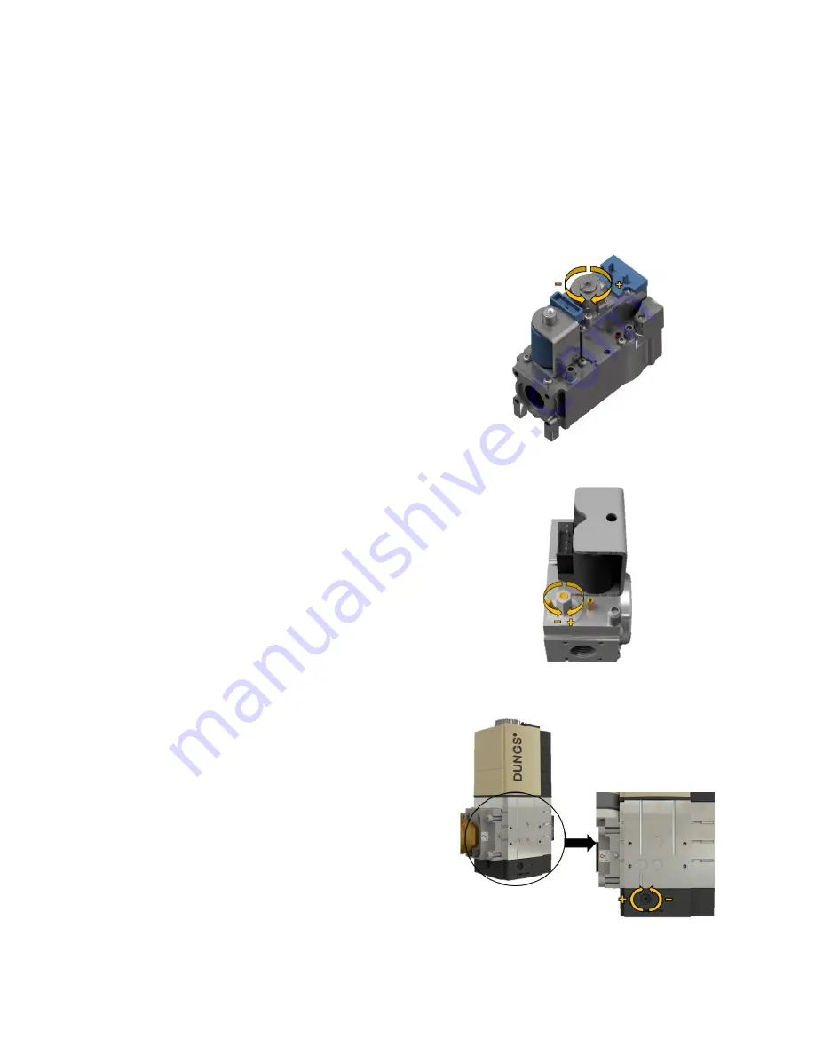
7. If the CO2 values need to be changed, find the low
fire trim on the gas valve, and rotate it clockwise
to increase CO2 and counterclockwise to
decrease CO2. Make sure the values are in the
range of table 11.
Figure 28: Low Fire Trim (VA0400)
Figure 29: Low Fire Trim (VA0500)
Figure 30: Low Fire Trim (VA0600, VA0725, VA0850)
Summary of Contents for Valiant-FT II Series
Page 2: ...99 0419 Rev 00...
Page 40: ...36 PART 9 PIPING DIAGRAMS Figure 40 Single Boiler Hydronic Heating Zoned Piping...
Page 41: ...37 Figure 41 Multiple Boiler Hydronic Heating Zoned Piping...
Page 42: ...38 Figure 42 Single Boiler with DHW Tank Hydronic Heating Zoned Piping...
Page 43: ...39 PART 10 PARTS LIST...
Page 44: ...40...
Page 45: ...41...
Page 46: ...42...
Page 47: ...43...
Page 48: ...44...
Page 49: ...45...
Page 50: ...46...
Page 51: ...47...
Page 52: ...48...
Page 53: ...49...
Page 54: ...50...
Page 60: ...56 PART 11 TUBING DIAGRAM...
Page 61: ...57 PART 12 WIRING DIAGRAM...
Page 62: ...58...
Page 63: ...59...


