Automatic Weather Station
with UT20 or UT30
Tower
Issued: 27.3.17
Copyright ©
2002
-2017 Campbell Scientific
Ltd.
CSL 164
INSTRUCTI
ON
MANUAL
Page 1: ...Automatic Weather Station with UT20 or UT30 Tower Issued 27 3 17 Copyright 2002 2017 Campbell Scientific Ltd CSL 164 INSTRUCTION MANUAL ...
Page 2: ......
Page 3: ...s under guarantee or not Please state the faults as clearly as possible and if the product is out of the guarantee period it should be accompanied by a purchase order Quotations for repairs can be given on request It is the policy of Campbell Scientific to protect the health of its employees and provide a safe working environment in support of this policy a Declaration of Hazardous Material and De...
Page 4: ......
Page 5: ...nt for recycling Any batteries contained within the product or used during the products life should be removed from the product and also be sent to an appropriate recycling facility Campbell Scientific Ltd can advise on the recycling of the equipment and in some cases arrange collection and the correct disposal of it although charges may apply for some items or territories For further advice or su...
Page 6: ......
Page 7: ...fore beginning work Wear a hardhat and eye protection and take other appropriate safety precautions while working on or around tripods and towers Do not climb tripods or towers at any time and prohibit climbing by other persons Take reasonable precautions to secure tripod and tower sites from trespassers Use only manufacturer recommended parts materials and tools Utility and Electrical You can be ...
Page 8: ......
Page 9: ...e Oasis Effect I 2 I 3 Obstructions I 3 I 4 The Effects of an Urban Environment I 3 I 5 Checking and Preparation I 3 Section 1 Site Preparation and Assembly of the Tower 1 1 1 1 Introduction 1 1 1 2 Description 1 3 1 2 1 Guying 1 3 1 3 Tower Specifications 1 3 1 3 1 Accessories 1 3 1 4 Site Preparation 1 4 1 5 Base Installation 1 4 1 5 1 Base Installation 1 4 1 5 2 Special RFM18 Base Installation ...
Page 10: ...cks 2 8 2 6 Tower Erection 2 8 2 6 1 Fitting Optional Guy Wires to Ground Anchors 2 9 2 7 Mounting Low Level Sensors and Other Equipment 2 10 2 7 1 Pyranometer 2 10 2 7 2 Temperature Relative Humidity Probe 2 10 2 7 3 Mounting the Enclosure 2 10 2 7 4 Mounting a Solar Panel 2 11 2 8 Connections 2 12 2 8 1 Power Supply Connections 2 12 2 8 2 Final Connections 2 12 2 9 Grounding and Lightning Protec...
Page 11: ... 2 3 Attaching the Top Tower Section 2 4 2 4 Sighting Along the Tower to Check the Magnetic Bearing 2 5 2 5 Weighting the Wind Sensor Perpendicular to the Ground 2 6 2 6 Both Mounting Arms and Sensors in Final Position on the Tower Mast Assembly 2 6 2 7 Installation of Guy Wires to Tower 2 8 2 8 Walking the Tower into the Upright Position 2 9 2 9 Installation of the Guy Wires to the Ground Anchors...
Page 12: ......
Page 13: ...nents The choice of location for your tower based weather station will depend on a number of circumstances and these are thoroughly discussed in Section I 1 of this manual After selecting a suitable site you must thoroughly check the general area for potential hazards which may occur during erection Ensure that ground conditions are suitable for the concrete bases which secure the tower anchor bol...
Page 14: ...ents while the tower is on the ground is given in Section 2 of this manual DO NOT CLIMB the tower whether guyed or unguyed for any reason Carry out the fitting and maintenance of all high level sensors with the tower on the ground as detailed later in this manual S 5 Maintenance S 5 1 Structure It is important to carry out maintenance at regular intervals as detailed in Section 2 of this manual in...
Page 15: ...cribes several factors which can affect the results obtained Please read through this information before deciding where to locate your AWS The descriptions in this introductory section are general rules for all types of weather stations and are not specific or exhaustive for any one type for further information please refer to meteorological publications The objective of any data collection exerci...
Page 16: ...e found in the meteorological literature I 2 1 The Clothesline Effect The clothesline effect in its simplest form describes the effect of air passing from dry unvegetated surfaces to moist vegetated surfaces and the consequent effect on vapour gradients and heat transfer This should be carefully considered when siting an AWS in crops or near trees when the wind direction is mostly towards the vege...
Page 17: ...on has a net radiometer be particularly cautious when siting it in a built up area as building temperature sky view factors and other variables affect the short wave and long wave components of the calculation of net radiation The impervious nature of an urban surface compared to surrounding rural areas together with the efficient channelling of water as surface run off leads to a generally drier ...
Page 18: ...ar Rustproofing compound for threads An adjustable spanner A range of standard and Phillips screwdrivers A compass for wind direction orientation Cable ties supplied A set of Allen hex keys at least a 3 16 Suitable lengths of appropriate cable for a The connection of the AC adaptors AC ADAPT and AC ADAPT2 to the PS100E charger and power supply unit b The interconnection of short haul modems c The ...
Page 19: ...ng the concrete base foundations Materials to make the foundations wood formers concrete mixture etc Wire rope cutter if using guy ropes on your installation A length of rope to assist in raising the tower There should be a minimum of two people on site for the safe installation and setting up of a complete tower based weather station ...
Page 20: ......
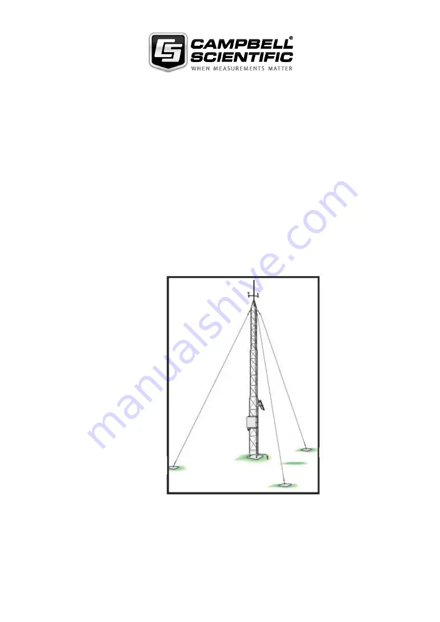
Page 21: ...g the tower where this is required and where the optional guying kit is provided 1 1 Introduction The UT20 and UT30 are tubular aluminium towers with two UT20 or three UT30 main sections plus a mast assembly giving an overall height of approximately 7 m and 10 m respectively The sections are triangular in cross section and consist of three aluminium tubes braced by continuous aluminium rod welded ...
Page 22: ...Figure 1 2 UT30 Tower Assembly with Enclosure Solar Panel and a Typical Range of Sensors Middle Section Mast Assembly Top Section Middle Section Bottom Section Hinged Mounting Base Assembly concreted into the ground Tower shown with optional guying kit ...
Page 23: ...nual gives full instructions for guying the tower where required Do not attempt to climb the structure whether guyed or not either to do initial installation or to carry out routine maintenance of components All installation and maintenance must be done with the tower at ground level as detailed in Section 2 of this manual 1 3 Tower Specifications Tower Model UT20 UT30 Total Height approx includin...
Page 24: ...o need to consider the positions of the guy anchors please refer to Section 1 6 below NEVER place any aluminium tower section directly into a concrete base The corrosive effects of the concrete on aluminium will damage the tower and void the warranty Use only the steel base leg assemblies as shown below You must also ensure good water drainage for the aluminium tubing on all the tower sections to ...
Page 25: ...hole periodically check that the tower is vertical using a spirit level and make adjustments as necessary Allow three to four days for the concrete to cure Figure 1 3 Bottom Tower Section and Base Installation 1 5 2 Special Roof Mounting Base Installation The roof mounting base has been designed for mounting to flat surfaces such as flat concrete slabs or flat roofs For installation you will need ...
Page 26: ...eg Stand the base and tower section upright and orient for the proper tilt direction see Figure 1 4 Install the base to the roof using three lag bolts or other anchors appropriate for the application see Caution above Before tightening the bolts check that the tower is vertical and add shims or other packing material to the base if necessary Figure 1 4 Special Roof Mounting Base Installation for U...
Page 27: ...e stake and scribe a circle with a 3 6 metre radius for UT20 or a 5 2 metre radius for UT30 3 Choose a tilt direction for the tower 4 From the centre point walk in the opposite direction and drive a stake into the ground on the scribed line see Figure 1 5 This marks the position of the rear leg anchor 5 Locate the other anchor points by measuring 6 2 metres UT20 or 9 metres UT30 from the rear towe...
Page 28: ...t level A pair of pliers Having previously installed the base and bottom tower section remove both bolts from the rear tower leg Remove the lower bolts and loosen the upper bolts in the other two legs so that the bottom tower section is free to hinge see Figure 1 3 Tilt the bottom tower section to the ground and assemble the middle section Note that only one bolt is required per leg for this there...
Page 29: ...embly 1 9 Figure 1 7 Fitting the Tower Sections 1 8 Fitting AWS Components and Erecting the Tower Section 2 of this manual details the fitting of sensors and other equipment and the final erection and guying of the tower Use one bolt per leg ...
Page 30: ......
Page 31: ...level to deter vandalism and give better exposure to light but this would make periodic maintenance such as cleaning more difficult and you may wish to mount such instruments at a lower level accessible directly from the ground or by using a step ladder 1 This manual does not cover sensors which will not be mounted on the tower itself e g tipping bucket raingauge or which are not part of a standar...
Page 32: ...following the advice given below in order to reduce the likelihood of measurement errors This section gives details of mounting the pyranometer to the top mast assembly This is the recommended mounting position for the pyranometer as it minimises any shading effects but you may wish to mount it elsewhere on the tower structure to facilitate maintenance see further comments below To ensure correct ...
Page 33: ...or fitting onto the main tower structure The following section gives details of mounting the pyranometer on the top mast assembly Section 2 7 describes mounting it on the tower structure at a lower level With the top tower section correctly levelled and oriented as shown in Figure 2 2 complete the assembly as follows 1 Attach the pyranometer to the levelling fixture 2 Fix the levelling fixture to ...
Page 34: ...er on the top mast assembly as described above you should mount the arm to face approximately south relative to the tower and always bear in mind and attempt to minimise any possible shading effects of the structure on the pyranometer See Section 2 6 2 3 2 Fitting the 011E Mounting Arm and Vector Instruments Wind Speed Direction Sensors The 011E cross arm sensor mount is supplied with a special tr...
Page 35: ...ded with the 011E arm to allow this In addition a nylon washer is supplied which can be used to stop the spacer and screw falling out of the mounting arm during installation 6 Weight the fin of the wind sensor by attaching a weight of some kind so that it is held perpendicular to the ground A makeshift weight might be a heavy bolt attached to the fin by two strips of adhesive insulating tape see F...
Page 36: ... correctly fitted as described above and in the sensor manuals Failure to do so can lead to false measurements or damage to the sensors 2 Do not attempt to remove the rotor of the wind speed sensor or the vane of the wind direction sensor while the sensors are fixed to the cross arm The correct procedure is described in the sensor manuals NOTE CAUTION Lightning Rod Assembly see Figure 2 1 011E Mou...
Page 37: ... and in Appendix A 2 3 4 018E Arm Wind Monitor and Pyranometer This arm is a combination of the 016E and 017E and is assembled in the same way as described for those arms starting with the pyranometer The 018E arm should be fitted together with the pyranometer before the tower top section is attached to the main tower structure as discussed in Section 2 3 1 above Ensure that the pyranometer end of...
Page 38: ... the position of the enclosure Always allow extra wiring for ease of assembly Attach the wiring to the tower with the cable ties Remember if you make an error you will probably have to lower the tower again to correct any problems so check all details carefully 2 6 Tower Erection After all the appropriate sensors have been fitted as outlined above the tower can be raised Carefully walk the tower s...
Page 39: ...while holding the tower vertical attach the guy wires to the eye end of the turnbuckles using one thimble and three U bolts per guy wire as shown in Figure 2 7 The U bolts should be fitted as shown at a spacing of 20 mm with the nuts on the live side of the guy wire Tighten the turnbuckles until it is just possible to pull the shackle by hand approximately 10 mm into the eye bolt as shown in Figur...
Page 40: ...g screws 2 7 2 Temperature Relative Humidity Probe The sensor can be inserted into the radiation shield before it is mounted on the tower This is done by loosening the large hexagonal nut and inserting the sensor into the shield twisting slightly if necessary until approximately 40 50 mm of the sensor tube is visible at the base of the shield Secure the sensor in position by tightening the large p...
Page 41: ...igure 2 10 below Figure 2 10 Fitting the Enclosure 2 Offer up the enclosure to the tower uprights and present the V bolts from the other side of the tubing to fit into the two matching central holes of the bracket 3 Tighten the V bolts up against the tower and brackets using the 6 mm nuts 2 7 4 Mounting a Solar Panel If you are using a solar panel with your weather station you will need to conside...
Page 42: ...nual With External Battery Please refer to the solar panel manual for full details Route the power cable from the external battery into the datalogger enclosure and connect it directly to the datalogger When connecting an SOP18 or a solar panel supplied with a separate regulator make sure you observe the correct polarity when connecting to the battery Incorrect connection can destroy the regulator...
Page 43: ...s Drive the spike into the ground using the Allen screw as a driving head Position the spike as close as possible to the base of the tower 2 Remove the Allen screw and screw the second spike into the straight connector Drive the second spike into the ground leaving about 100 mm exposed above ground This will drive the first spike to a depth of about 2 3 m into the ground and should provide a good ...
Page 44: ...ther station is installed at a site where frequent direct lightning strikes are likely Campbell Scientific recommends that you seek the advice of a specialist lightning protection company 2 10 Maintenance 2 10 1 Enclosure 1 Referring to the ENC 10 12 ENC12 14 and AM ENC Enclosures Installation Manual seal the cable gland if it is used for cable entry Do not use bath or tile sealant which gives off...
Page 45: ...ection 1 2 10 3 Inspection After a few days check that the tower is secure and level Check the guy wires where fitted and all bolts At least every year and preferably every six months check the tower for tilting and damage check all guy wires where fitted and reapply rustproofing compound as before especially around the eyebolts The desiccant pack in the enclosure should be changed or dried out at...
Page 46: ...ensors is necessary you may have to remove the top section of the mast and proceed as outlined in Section 2 3 of this manual After all necessary maintenance has been carried out re erect the tower following the procedures given in Section 2 6 Re check all three guy wires for security and carry out any other maintenance such as rust prevention as detailed above Low Level Sensors and equipment If yo...
Page 47: ...ser Guide use the datalogger program as follows 1 Set up the link between your PC and the datalogger The simplest method is a direct link using the SC32B opto isolated interface or an SC929 Interface Cable Refer to the manuals for the interface you are using for connection details No separate interface is required for the CR23X CR3000 or CR1000 If you intend to use a different link such as a telep...
Page 48: ...all the functions of PC200W PC400 or LoggerNet are contained in the User Guide for the software Campbell Scientific dataloggers can be programmed from a computer without using the datalogger support software by using telecommunications commands However this is not normally necessary and is not recommended as a general method of datalogger programming NOTE ...
Page 49: ...etic north is easily corrected by adding or subtracting the difference between the two readings as explained below Maps are always drawn in relation to the true north pole and ordnance survey maps will normally show the offset or declination angle between true and magnetic north To find true north bearing for a specific site do the following 1 First establish the declination angle or offset betwee...
Page 50: ...th the magnetic north bearing to set the wind sensor to true north as explained in Section 2 3 of this manual NOTE Declination angles for True North to the West of Magnetic North are subtracted from 360 therefore True North reading is 360 15 345 for this specific case MAGNETIC NORTH COMPASS NEEDLE POINTS TO MAGNETIC NORTH TRUE NORTH map bearing 15 WEST OF MAGNETIC NORTH Point the wind direction se...
Page 51: ......
Page 52: ...NW Edmonton Alberta T5L 4X4 CANADA www campbellsci ca dataloggers campbellsci ca Campbell Scientific Centro Caribe S A CSCC 300N Cementerio Edificio Breller Santo Domingo Heredia 40305 COSTA RICA www campbellsci cc info campbellsci cc Campbell Scientific Ltd CSL 80 Hathern Road Shepshed Loughborough LE12 9GX UNITED KINGDOM www campbellsci co uk sales campbellsci co uk Campbell Scientific Ltd Franc...