Appendix B. Installation Scenarios
B-3
Master
RF451
Slave
Slave
Slave/
Repeater
PC Running
LoggerNet
/PC400
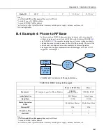
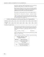
FIGURE B-3. Schematic of PC-to-RF451 Network with Repeater
Using
DevConfig,
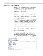
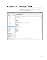
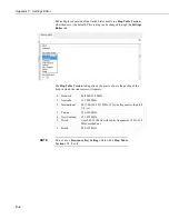
set up the master, slave/repeater RF451, and slave RF451
radios according to TABLE
below. The
Deployment
tabs of
DevConfig
should look similar to FIGURE
through FIGURE
TABLE B-2. RF451 Settings for Example 2
Master
Slave/Repeater
Slave(s)
Hardware
RF451 connected to PC
running
LoggerNet
RF451 connected to CR1000
CS I/O port
RF451 connected to
CR1000 CS I/O port
PakBus
Address
4094
2
3
Keep all factory default settings except:
Active
Interface
USB or RS-232 (to match
how
LoggerNet
will be
communicating with the
radio)
CS I/O SDC (with SDC
Address set to an unused SDC
address on the datalogger)
CS I/O SDC (with SDC
Address set to an unused
SDC address on the
datalogger)
Radio
Operation
Mode
Multi-Point Master
Multi-Point Slave/Repeater
Multi-Point Slave
Repeaters
Used
Yes, check box
Yes, check box
Yes, check box
Network ID
1726 (yours may be different) 1726 (yours may be different)
1726 (yours may be
different)
Frequency
Key
1 (yours may be different)
1 (yours may be different)
1 (yours may be different)
Radio ID
4094 (to match
LoggerNet
PakBus address)
2 (to match CR1000 PakBus
address)*
3 (to match CR1000
PakBus address)*
* All slave radios in the network will have these same settings except for the
Radio ID
. The
Radio ID
should
match the PakBus address of the datalogger it is connected to.
Summary of Contents for RF451
Page 2: ......
Page 6: ......
Page 10: ...Table of Contents iv ...
Page 34: ...RF451 Spread Spectrum Radio 24 ...
Page 36: ......
Page 46: ...Appendix B Installation Scenarios B 10 ...
Page 58: ...Appendix D Distance vs Antenna Gain Terrain and Other Factors D 10 ...
Page 60: ......
Page 61: ......


