background image

Section 4.  ET106 Sensor Arm Installation

4-8

1

Not Used

Connector

Pin

Magnetically

Activated Reed

Switch

Tipping Rain Bucket

Not Used

Not Used

Ground

Pulse

Datalogger

Shield

2

4

3

P2

G

G

5

6

1

2

3

4

5

6

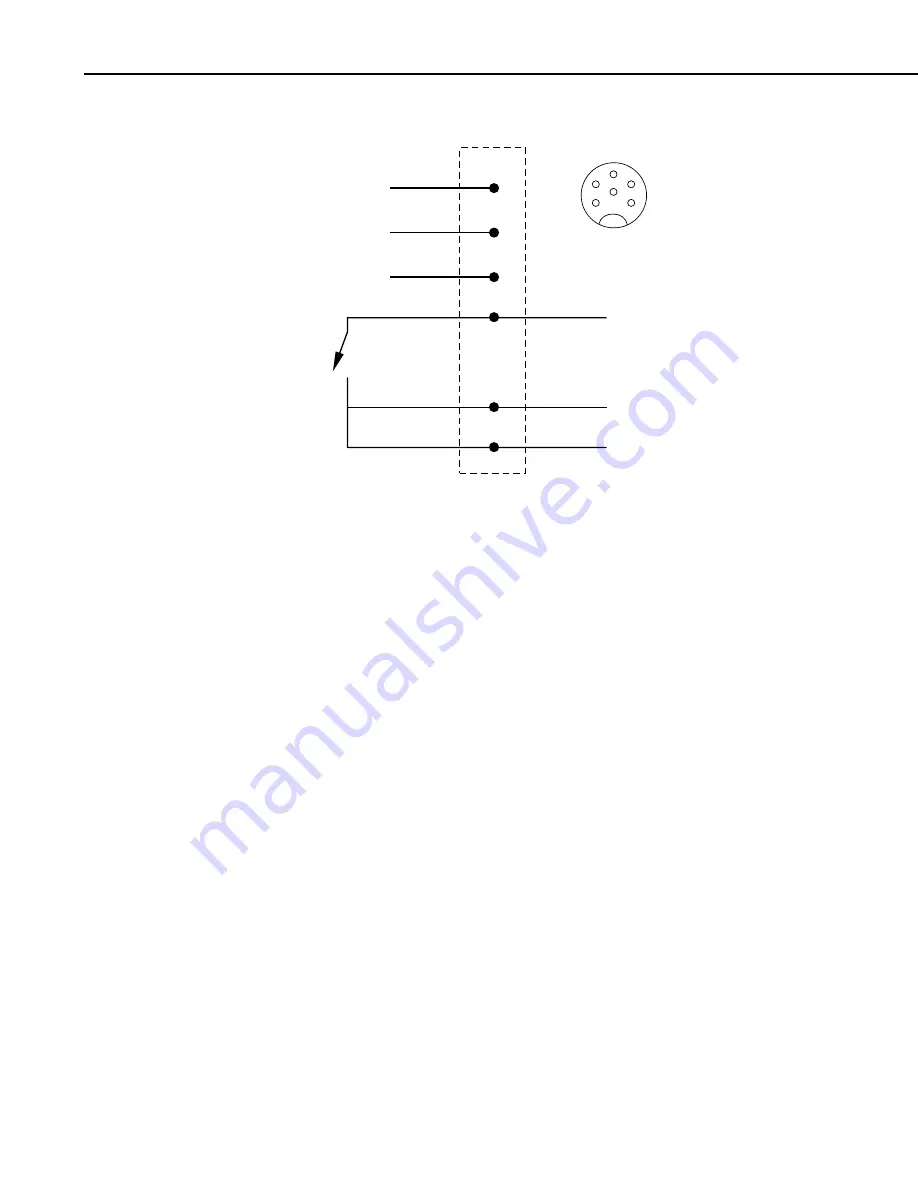
FIGURE 4.10-4.  Schematic of TE525-LC Rain Sensor and Connector #5

Summary of Contents for ET106

Page 1: ...INSTRUCTION MANUAL ET106 Weather Station Revision 9 02 C o p y r i g h t c 1 9 9 3 2 0 0 2 C a m p b e l l S c i e n t i f i c I n c...

Page 2: ...er warranties expressed or implied including warranties of merchantability or fitness for a particular purpose CAMPBELL SCIENTIFIC INC is not liable for special indirect incidental or consequential da...

Page 3: ...on Installation 3 1 3 1 Enclosure Datalogger Power Supply 3 2 3 2 Sensor Connection 3 5 3 3 Communication and Data Storage Peripherals 3 6 3 4 Sealing and Desiccating the Enclosure 3 12 4 ET106 Sensor...

Page 4: ...This is a blank page...

Page 5: ...r communications device and power supply in enclosure Section 3 Install datalogger support software on PC Section 5 Establish communications between the datalogger and the PC Section 5 Program datalog...

Page 6: ...Tools Required Tools required to install and maintain a weather station are listed below 1 2 1 Tools for Tower Installation All Towers Shovel Rake Open end wrenches 3 8 7 16 2 9 16 Magnetic compass 6...

Page 7: ...als for B18 Base and UTEYE Anchors 4 Wood stakes 12 Pick or digging bar Concrete form materials 2 x 4 lumber stakes saw hammer nails etc Concrete trowel and edger Materials for UTDUK Duckbill Anchors...

Page 8: ...flon tape or pipe dope 12 1 4 washers for the 015 Crossarm stand only Allen wrench set UT30 Tape measure 12 to 20 3 8 nut driver Level 36 to 48 Pliers Climbing harness Hard hats 50 haul rope Crescent...

Page 9: ...peed and Direction Wind sensors should be located over open level terrain and at a distance of at least ten times EPA the height of any nearby building tree or other obstruction as illustrated in Figu...

Page 10: ...ation The gage must be mounted above the average level of snow accumulation in areas that experience significant snowfall Standard measurement heights 1 0 m 1 0 cm AASC 30 0 cm minimum WMO EPA 1 3 4 S...

Page 11: ...een True North and Magnetic North Magnetic declination for a specific site can be obtained from a USFA map local airport or through an internet service called NSSDC CGM Section 1 4 1 A general map sho...

Page 12: ...de of your site fill out Form 1as shown below for an accurate magnetic declination If you do not know the latitude and longitude of your site fill out Form 2 for estimate of magnetic declination Note...

Page 13: ...its location in the table A positive declination is east while a negative declination is west The declination in this example is 14 417 degrees As shown in Figure 1 4 1 the declination for Logan UT i...

Page 14: ...orological Instruments and Methods of Observation World Meteorological Organization No 8 5th edition Geneva Switzerland 3 The State Climatologist 1985 Publication of the American Association of State...

Page 15: ...ort structure for mounting the ET101 and ET106 weather station components Figure 2 1 1 shows a typical ET Tower installation option The tower is designed to withstand winds of 100 mph The lightning ro...

Page 16: ...conduit Make certain the cavity points in the direction from which power and communications cables will come 6 Center the form over the hole Adjacent to the form drive four stakes into the soil Secur...

Page 17: ...Section 1 for components supplied by installer 2 2 2 Installation Attach the tower to the base as shown in Figure 2 2 1 1 Dig a hole close to the concrete base to access the lower conduit opening From...

Page 18: ...lower it onto the conduit and mounting bolts Install a washer and nut on each bolt and hand tighten Check plumb of the tower by placing a level on the north and east sides of the lower tower section A...

Page 19: ...he foundation using a fence post driver or sledge hammer Drive the rod at an angle if an impenetrable hardpan layer exists Soften hard clay soils with water if necessary 3 Strip 1 inch of insulation f...

Page 20: ...Section 2 ET Tower Installation 2 6 This is a blank page...

Page 21: ...are mounted in the ET enclosure at the locations shown in Figure 3 1 Components include 1 ET Enclosure 1 4 unit Desiccant Pack 1 Flat Point Screw Driver 1 Power Supply Option 1 Telecommunications Opti...

Page 22: ...NAL BATTERY MADE IN USA 12V ALKALINE BATTERY PACK BPALK Logan Utah TEMPORARY BATTERY FIGURE 3 1 1 Alkaline Power Mounting and Connections YUASA FIGURE 3 1 2 Rechargeable Power Mounting and Connections...

Page 23: ...titude Tilt Angle 0 to 10 degrees 10 degrees 11 to 20 Latitude 5 degrees 21 to 45 Latitude 10 degrees 46 to 65 Latitude 15 degrees 65 80 degrees b After determining the tilt angle loosen the two bolts...

Page 24: ...3 1 4 Mounting and Grounding the ET Enclosure c Slide the enclosure to the top of the ET tower Position it on the north side of the tower northern hemisphere The top of the enclosure should be flush w...

Page 25: ...sure by removing the two Phillips head screws Sensors connect to one of seven labeled bulkhead connectors as shown in Figure 3 2 1 Earth Ground Stand off Connector 4 Sensors TEMP CS615 TEMP RAIN PRECI...

Page 26: ...wired no further connections inside the enclosure are necessary Follow the External Installation procedures outlined below to make the external connections If you received a telecommunications kit sep...

Page 27: ...dem ground port to the ET Enclosure ground with the 14 AWG ground wire 3 3 1 2 External Installation The following modem kit components are used to make the external connections 1 Direct Bury Splice K...

Page 28: ...RJ11C Interface to the side of the battery bracket 3 Connect the modem 9 pin port to the ET Enclosure port with the blue 9 pin ribbon cable supplied with the ET Enclosure 4 Connect the modem RJ ll ja...

Page 29: ...Connector normally not used Power Indicator do not press RJ11C Interface Coax Bulkhead Connector Battery Motorola M600 Transceiver COM200 or VS1 Telephone Modem Green Modem Ground Wire to Recessed GN...

Page 30: ...s shown in Figure 3 3 3 2 Connect the antenna to the external coaxial bulkhead connector with the 9 foot antenna cable 3 3 3 Short Haul Modem Short haul modems enable communication between a datalogge...

Page 31: ...h cord Match wire labels to wiring panel labels on both the ET Enclosure and the Rad Modem XMT to XMT etc A small screwdriver in provided with the ET Enclosure to access the Rad Modem connections 3 3...

Page 32: ...ET106 ENCLOSURE ET106 ENCLOSURE To 8 External Connector Earth Ground C A M P B E L L S C I E N T I F I C L T D S C 9 3 2 S N E 1 0 5 5 Q C FIGURE 3 3 5 Short Haul Modem Wiring Diagram 3 4 Sealing and...

Page 33: ...T 250 F DESICCANT ACTIVATED BAGGED FOR CONTENTS 4 UNITS PACKAGE USE AND STATIC DEHUMIDIFICATION DO NOT EAT UNITED DESICCANTS GATES 101CHRISTINE BELEN NEW MEXICO 87002 DESI PAK SPECIFICATION MIL D 3464...

Page 34: ...Section 3 ET Instrumentation Installation 3 14 This is a blank page...

Page 35: ...wind sensor attached Screws 4 FIGURE 4 2 1 ET106 Sensor Arm Mounting 1 Remove the cover from the ET Enclosure 2 Place the sensor arm on top of the enclosure lining up the four threaded holes on the un...

Page 36: ...the 034A in the 034A Mounting Shaft pointing the vane due south Tighten the alignment screw 2 Attach the 034A and mounting shaft to the sensor arm Insert the mounting shaft into the U bolt clamp Adju...

Page 37: ...l the bubble level indicates plumb Remove the red cap from the pyranometer FIGURE 4 6 1 Pyranometer Leveling 4 7 Soil Temperature Sensor Optional Bury the soil temperature sensor at the desired depth...

Page 38: ...using the 5 mode with the CR10KD refer to the laminated prompt sheet 4 9 Upgrading an ET101 to an ET106 The ET101 can be upgraded to an ET106 by installing part number 10574 ET101 to ET106 Upgrade Kit...

Page 39: ...Section 4 ET106 Sensor Arm Installation 4 5 Logan Utah MADE IN USA ET101 to ET106 FIGURE 4 9 1 Upgrading the ET101 to an ET106 FIGURE 4 9 2 Modifying the Pyranometer Plate...

Page 40: ...p in troubleshooting Knowledge of the schematics is not necessary for routine installation and maintenance 1 2 3 4 5 6 Air Temperature and Relative Humidity Sensor Connector Pin Datalogger Relative Hu...

Page 41: ...Excitation 10K OHM 10K OHM Potentiometer 1K OHM Datalogger Shield 1 2 4 P1 AG 2H E2 G G 5 6 1 2 3 4 5 6 FIGURE 4 10 2 Schematic of 034A LC Wind Speed and Direction Probe and Connector 2 Solar Radiatio...

Page 42: ...lation 4 8 1 Not Used Connector Pin Magnetically Activated Reed Switch Tipping Rain Bucket Not Used Not Used Ground Pulse Datalogger Shield 2 4 3 P2 G G 5 6 1 2 3 4 5 6 FIGURE 4 10 4 Schematic of TE52...

Page 43: ...20 manual 2 Create the ET datalogger program by clicking your mouse cursor on the main screen Edit then on Create Station Program Edit Create Station Program Follow the prompts until you return to the...

Page 44: ...Section 5 ET Software Installation 5 2 This is a blank page...

Page 45: ...ogger failure 6 1 2 Batteries Instruction 10 can be used to measure battery voltage By recording battery voltage the user can determine how long a fresh set of batteries will last see the Installation...

Page 46: ...onditions 6 1 4 Sensor Maintenance Sensor maintenance should be performed at regular intervals depending on the desired accuracy and the conditions of use A suggested maintenance schedule is outlined...

Page 47: ...he battery has been installed and the power switch if any is ON Section 7 B Use a voltmeter to measure the voltage on the 12 V and G terminals the voltage must be between 9 6 and 16 VDC C Disconnect a...

Page 48: ...99999 Displayed in an Input Location A Make sure the battery voltage is between 9 6 and 16 VDC B With the MetData1 or ET106 verify that the sensor is connected to the proper bulkhead connector With c...

Page 49: ...2 5 6999 or 99999 Stored in Final Storage or Storage Module A Final Storage format limitations exceeded any number larger than 6999 in low resolution or 99999 in high resolution format is stored as t...

Page 50: ...Section 6 Maintenance and Troubleshooting 6 6 This is a blank page...

Page 51: ...This is a blank page...

Page 52: ...campbellsci com br suporte campbellsci com br Campbell Scientific Canada Corp CSC 11564 149th Street NW Edmonton Alberta T5M 1W7 CANADA www campbellsci ca dataloggers campbellsci ca Campbell Scientifi...

Reviews: