


CSAT3B Three-Dimensional Sonic Anemometer
49
FIGURE 8-2. Measurement settings in
Device Configuration Utility
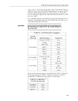
TABLE 8-1. Overview of CSAT3B Operating Modes
Mode
Measurement Trigger
Filters
Output Prompt
Source
Rate
Enabled Bandwidth (Hz)
Source
Rate
0
Data logger
1 to 100 Hz
1/
No
-
Data logger
1 to 100 Hz
1/
1
CSAT3B
100 Hz
Yes
5, 10, 20, 25
Data logger
1 to 100 Hz
1/
2
CSAT3B
100 Hz
No
-
CSAT3B
10, 20, 50, 100 Hz
3
CSAT3B
100 Hz
Yes
5, 10, 20, 25
CSAT3B
10, 20, 50, 100 Hz
1/
The exact rate is determined by the scan interval set in the CRBasic program of the
data logger.
Data logger prompted output using Mode 0 requires use of SDM
or CPI communications. Data logger prompted output using
Mode 1 requires CPI communications (SDM not compatible with
bandwidth filters). The options for unprompted output to a
computer require use of RS-485 or USB communications.
NOTE