


CSAT3B Three-Dimensional Sonic Anemometer
52
Mode 1
In the case where the CSAT3B is self triggered and filtered, the output data can
still be collected by a data logger (Mode 1) using CPI communications. In this
case, the data logger will prompt the CSAT3B for an output each time it
executes the
CSAT3B() CRBasic
instruction in the program scan. When the
data logger prompt is received by the CSAT3B, it will output the most recent
100 Hz filtered sample in its buffer to the data logger. This filtered data is
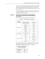
delayed by a certain time interval (given in TABLE
) and should be taken
into account when aligning with other fast-response sensors. There are
additional synchronicity considerations. Because the measurement was not
triggered by the data logger according to its own clock, the sample received by
the data logger may have a small synchronicity error between
−
5 and + 5
milliseconds with respect to the data logger’s timestamp. The actual error
depends on the operational mode and the output rate, as shown in TABLE
Mode 1 (bandwidth filter and data logger prompted sampling) is
only compatible with CPI communications.
Modes 2 and 3
If the CSAT3B measurements are to be self triggered and output to a computer,
as in Modes 2 and 3, an unprompted output operating mode should be selected.
Available output rates for the CSAT3B are 10, 20, 50, or 100 Hz. In
unprompted mode, the CSAT3B will downsample or decimate the 100 Hz
buffer data (unfiltered or filtered, depending on whether the user has selected
Mode 2 or Mode 3, respectively) to output at the appropriate rate. The
unprompted output record is an ASCII string of comma-delimited data
terminated by a carriage return and contains the following seven data fields:
1)
u
x
– x-axis wind speed in meters per second (m·s
–1
)
2)
u
y
– y-axis wind speed in meters per second (m·s
–1
)
3)
u
z
– z-axis wind speed in meters per second (m·s
–1
)
4)
T
s
– Sonic temperature in degrees Celsius (°C)
5)
Diagnostic word
6)
Record counter
7)
Signature
The record counter is a decimal value that is incremented each record until
reaching a maximum value of 63, at which point it starts back over at zero. The
counter may be used to ensure each record is not a duplicate of the last and that
a record has not been omitted.
The final data field in each record is the signature, a four character
hexadecimal value that is a function of the specific sequence and number of
bytes in the output array. The computer may calculate its own signature using
each transmitted byte until reaching the signature data field. The computed
signature and the transmitted signature are compared. If they match, the data
were received correctly. This is very similar to a Cyclic-Redundancy-Check
(CRC).
Signature checking is done automatically by a data logger when
using SMD or CPI communications and does not require extra
programming by the user.
NOTE
NOTE