


CMP6-L, CMP11-L, and CMP21-L Pyranometers
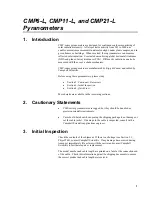
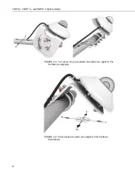
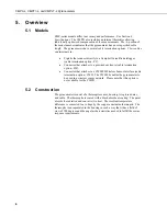
FIGURE 7-3. Exploded view of the pyranometer mounting
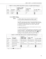
7.2 Wiring
Short Cut users should wire the sensor according to the wiring
diagram generated by Short Cut.
The cable of the CMP6 and CMP11 has two conductors and a shield. The
cable of the CMP21 has five conductors and a shield. The additional
conductors on the CMP21’s cable are for connecting its internal thermistor. A
schematic for the CMP6, CMP11, and the thermopile of the CMP21 is
provided in Section 7.2.1,
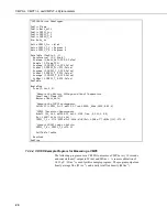
CMP6, CMP11, and CMP21 Thermopile Schematic
.
Wiring for the CMP6 and CMP11 is described in Section 7.2.2,
CMP6 and
CMP11 Wiring
, wiring for the CMP21 is described in Section 7.2.3,
CMP21
Wiring
.
NOTE
Mounting screws
Levelling screw
CM2
mounting st
45
and
Pyranometer
Crossarm
Bubble level
Nylon washers
Sun shield
11
Summary of Contents for CMP11-L
Page 2: ......
Page 8: ...Table of Contents iv ...
Page 34: ...CMP6 L CMP11 L and CMP21 L Pyranometers 26 ...
Page 40: ...Appendix A CVF3 Heater Ventilator A 6 ...
Page 41: ......


