INSTRUCTION MANUAL
Copyright © 2007
Campbell Scientific (Canada)Corp.
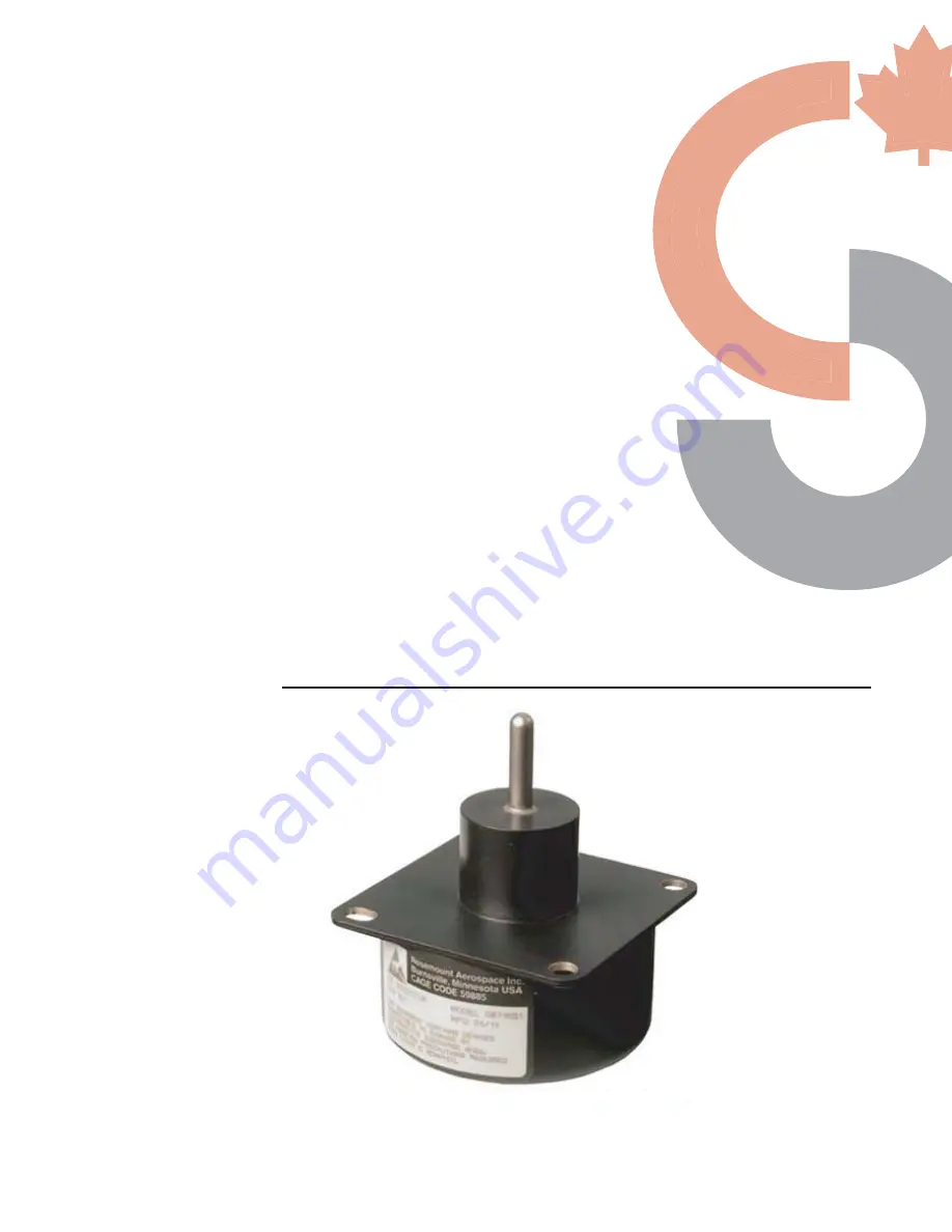
0871LH1
Freezing Rain Sensor
December
2008
Page 1: ...INSTRUCTION MANUAL Copyright 2007 Campbell Scientific Canada Corp 0871LH1 Freezing Rain Sensor December 2008 ...
Page 2: ...eglect accidents of nature or shipping damage This warranty is in lieu of all other warranties expressed or implied including warranties of merchantability or fitness for a particular purpose CSC is not liable for special indirect incidental or consequential damages Products may not be returned without prior authorization To obtain a Return Merchandise Authorization RMA contact CAMPBELL SCIENTIFIC...
Page 3: ...12 5 BIT Failure That Disables Ice Output 13 6 Operator Initiated Tests 14 7 Initiated Built In Test BIT 15 8 Correlation Counting 16 9 Ice Detector RS 422 String Format 17 10 Electrostatic Discharge ESD Consideration 19 APPENDIX B 1 Freezing Rain Sensor Block Diagram 20 1 1 Microcontroller 21 1 2 Watchdog Reset Circuit 21 1 3 Serial EEPROM 21 1 4 Probe Oscillator 21 1 5 Heater Control 22 1 6 Driv...
Page 4: ...1 MSO Circuit Schematic 5 Figure 2 MSO Circuit Sectional View 5 Figure 3 Freezing Rain Sensor 6 Figure 4 Mounting 7 Figure 5 Power Supply Connections 8 Figure 6 General Hook up Diagram 8 Figure 7 Functional Block Diagram 20 2 ...
Page 5: ...inciple of Operation The freezing rain sensor uses an ultrasonically axially vibrating probe to detect the presence of icing conditions The sensing probe is a nickel alloy tube mounted in the strut at its midpoint node with one inch exposed to the elements This tube exhibits magnetostrictive properties it expands and contracts under the influence of a variable magnetic field A magnet mounted insid...
Page 6: ...a few seconds and is ready to sense ice formation again When ice forms on the sensing probe again to the point where the MSO frequency decreases by 130 Hz the sensor de ices itself again This cyclic process is repeated as long as the freezing rain sensor remains in an icing environment The ice signal activates at 0 020 ice accretion and stays on for 60 seconds after the end of the icing encounter ...
Page 7: ...Figure 1 MSO Circuit Schematic Figure 2 MSO Circuit Sectional View 5 ...
Page 8: ...of unit malfunction causing strut heater lock on the probe temperature can exceed 204 4 C Maintenance personnel should exercise caution when servicing the unit 6 Power Interruptions The freezing rain sensor is qualified to DO 160C power input category Z The unit will remember status through a 200 ms power interruption but the output string will cease during the interruption The freezing rain senso...
Page 9: ... rain sensor to the mounting bracket using the supplied 20 screws and lock washers Position the freezing rain sensor on the mounting pole with the sensing probe pointing upward with the bracket inclined at a 20 30 angle above horizontal to ensure proper drainage of melted ice 3 Attach to a vertical or horizontal pipe using the supplied V bolts nuts and washers NOTE The sensor should be mounted so ...
Page 10: ...Blue Control Port Control Port Status Yellow Control Port Control Port Power Reference Black G G Case GND Green G G 5V Power Purple 5V 5V Shield Clear G G cannot share control ports Figure 5 Power Supply Connections part C2155 Figure 6 General Hook up Diagram Power Connections to Terminal Expander 24 VDC Red V 24V Black V ...
Page 11: ...c IceStat 5 Read Ports P25 1 2 Mask 0 255 2 1 Loc FaultStat Check to see if there is a fault in the unit and output it 6 If X F P89 1 1 X Loc FaultStat 2 1 3 1 F 4 30 Then Do 7 Do P86 1 10 Set Output Flag High Flag 0 8 Set Active Storage Area P80 3085 1 1 Final Storage Area 1 2 10 Array ID 9 Real Time P77 1712 1 1220 Year Day Hour Minute midnight 2400 10 Sample P70 23951 1 1 Reps 2 1 Loc FaultStat...
Page 12: ...that ends only when ice is no longer detected 17 Timer P26 1 0 Reset Timer 18 End P95 19 End P95 9 2 CR1000 Declare Public Variables Public PTemp batt_volt Public TimeCount Public IceSignal Public StatusSignal ice signal 1 no ice 0 ice status signal 0 okay 1 fault Define Data Tables DataTable Stat True 1 Sample 1 StatusSignal FP2 EndTable DataTable Ice True 1 Sample 1 IceSignal FP2 EndTable DataTa...
Page 13: ...Temp 250 Battery Batt_volt TimeCount Timer 1 Sec 0 If TimeCount 61 then Portget IceSignal 1 PortGet StatusSignal 2 If StatusSignal 1 then CallTable Stat EndIf If IceSignal 0 then CallTable Ice Timer 1 Sec 3 EndIf EndIf CallTable Info NextScan EndProg ...
Page 14: ...sabled Failures detected in Initiated and Continuous BIT are counted and enunciated once they have been verified To eliminate nuisance errors failures are verified by delaying debouncing the failure for a period of time Failures detected in Initiated BIT are latched and power must be cycled on and off to remove a failure If failures detected in Continuous BIT go away the ice detector changes back ...
Page 15: ...ween 39000 and 40150 Hz are valid The probe heater is de icing correctly After turn on the probe heater must cause the MSO frequency to return to at least 39970 Hz within the 25 second timeout or it is considered failed Probe is de iced within 25 seconds De Icing Fail 5 BIT Failure That Disables Ice Output The Ice output is disabled due to Continuous and Initiated BIT failures as shown in Table 1 ...
Page 16: ... de icing failure has been detected If the frequency indicates that the ice has been removed within the expected time the software will not annunciate the probe heater failure The actual failure is most likely due to a problem in the heater feedback circuitry rather than heater control circuitry The failure will be enunciated the next time IBIT is performed 6 Operator Initiated Tests The operator ...
Page 17: ...ring and on the discrete outputs so monitoring electronics or test equipment can verify activation The freezing rain sensor heater is turned on for a short period of time to verify correct operation of the heater heater control circuit and heater feedback circuit Correct operation of the watchdog timer is verified by simulating a microcontroller time out and waiting for a reset input Proper ROM op...
Page 18: ...an icing enoucnter The correlation count is a value tracked by the freezing rain sensor that indicates the amount of ice that has accumulated on the probe during the icing encounter Each correlation count equals 0 010 inches of ice The correlation count ranging from 0 to 255 indicates the number of times the MSO frequency decreases by 65 Hz during an icing encounter A decrease in frequency of 65 H...
Page 19: ... 0 No Ice 0 Status Output 1 Fail 0 OK No Fail 1 2 MSO FREQUENCY MSO Count in Hex Frequency 774060000 Dec MSO 3 ERRSTAT1 7 Unused 1 Active 6 MSA Fail Too High 5 MSO Fail Too Low 4 EEPROM Fail 3 RAM Fail 2 ROM Fail 1 Watchdog Fail 0 Power Interrupt Timer Fail 4 ERRSTAT2 7 6 Probe Heater Failure 00 Probe Heater OK 01 Probe Heater Always ON or OPEN 10 Probe Heater Always OFF 11 Probe Heater ON with 1 ...
Page 20: ...FF 13 FAIL DTL 1 7 4 MSO Frequency Fail Count 0 F 3 0 Heater Fail Count 0 F 14 FAIL DTL 2 7 4 Not Used Not Used 3 0 Not Used Not Used 15 LAST ERR 1 See ERRSTAT1 Above 16 LAST ERR 2 See ERRSTAT2 Above 17 2ND LAST ERR 1 See ERRSTAT1 Above 18 2ND LAST ERR 2 See ERRSTAT2 Above 19 PERM ERR 1 See ERRSTAT1 Above 20 PERM ERR 2 See ERRSTAT2 Above 21 Software Version 7 0 Software Version per VDD SC1 0 FF 22...
Page 21: ...Electrostatic Discharge ESD Consideration The freezing rain sensor internal components are ESD sensitive class 1 so proper ESD precautions must be observed wrist straps conductive surfaces when handling 19 ...
Page 22: ...ix B 1 Freezing Rain Sensor Block Diagram The block diagram in Figure 4 Functional Block Diagram provides an understanding of the functionality of the freezing rain sensor Figure 7 Functional Block Diagram 20 ...
Page 23: ... state correlation count which is recovered after power interruptions of 200 ms or less This allows the unit to meet the power interruption requirements of RTCA DC 160C Section 16 Category Z Additionally the Serial EEPROM stores environmental and failure information such as unit elapsed time number of icing encounters number of failures and detailed information on types and quantities of each annu...
Page 24: ...e feedback coil senses the movement of the probe and when employed in the probe oscillator circuit completes the feedback portion of the MSO 1 8 Heater The probe heater de ices the probe It is activated when the nominal icing trip point of 0 020 is reached and is turned off five seconds after the MSO has returned to at least 39 970 Hz the additional five seconds allows the strut probe time to shed...
Page 25: ...quency drop of 130 Hz equivalent to approximately 0 020 ice formation If the frequency subsequently decreases by 130 Hz while the Ice Signal output timer is non zero the timer is reinitialized to 60 seconds The output is transient protected to meet RTCA DO 160C lightning requirements and to prevent stray high voltage from coupling into the unit and damaging the output transistor The ice output has...
Page 26: ...y DO 160C Shock Salt Spray DO 160C Cat S Humidity DO 160C Cat B Icing Performance Rosemount Aerospace Inc Test Procedure Power Input DO 160C Cat Z 18 29 5 VDC Voltage Spike DO 160C Cat A Magnetic Effect DO 160C Cat A 1 deflection at 0 5m 2 5 mΩ Max Mounting Plate to Aircraft Structure Bonding 10 mΩ Max Connector Shell to Mounting Plate Dielectric Withstanding MIL STD 202 500 VAC 60 Hz EMI Filters ...
Page 27: ...urn B Input 20 Case Ground C Input 20 RS 422 High D Output Per RS 422 Spec Per RS 422 Spec 20 24 RS 422 Low E Output Per RS 422 Spec Per RS 422 Spec 20 24 Ice F Output Ground Active 1 5 VDC Max 0 5 50 mA 20 24 Open Inactive Status G Output Ground Active 1 5 VDC Max 0 5 50 mA 20 24 Open Inactive Ice will be correctly detected between these voltages Proper probe de icing however is only guaranteed w...