A-5
Scanner
®
2000 microEFM
Appendix A
!
WARNING: When a hazardous area is present, ensure the union nut and blanking plug a prop-
erly fitted in the conduit opening. The hazardous location rating applies only when the union
nut and blanking plug are secured in place. When the union is broken, the device is no longer
explosion-proof.
!
WARNING: Before disassembling the union nut and blanking plug, make sure the area is non-
hazardous.
To connect a PC or laptop to the communications adapter, perform the following steps:
1. Unscrew the union nut to expose the connector socket shown in
. A blanking plug will
be removed with the union nut. Store the union nut and blanking plug in a safe place. (They will need to
be reinstalled when the adapter is not in use.)
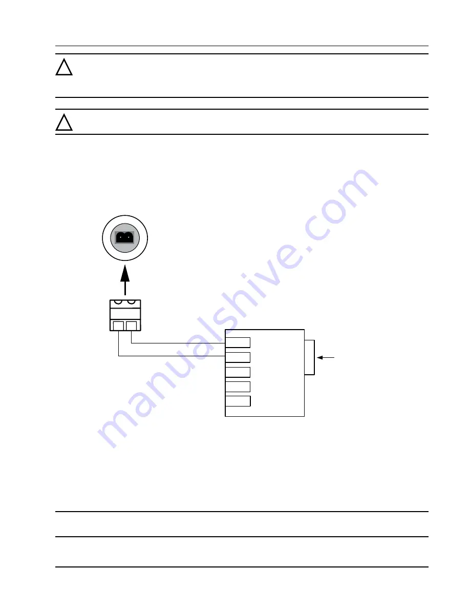
2. Connect the plug connector to an RS-485 converter cable, if it is not already attached (Figure A.9).
PLUG CONNECTOR
(LEFT AND RIGHT WIRE POSITIONS ARE VALID ONLY
WHEN PLUG IS FACING SOCKET IN POSITION SHOWN)
COM ADAPTER SOCKET
RS-485
CONVERTER
RS-232 9-PIN
CONNECTOR
TD(A)
TD(B)
GND
Part No. 101283116
GND
+12V
Figure A.9—Wiring of plug connector to Cameron 9-pin RS-232 to RS-485 converter cable
3. Insert the plug connector into the adapter socket.
4. Connect the converter cable to the PC or laptop.
To disconnect the adapter, remove the plug connector (with converter cable attached) from the socket, place
the blanking plug inside the union nut (removed in step 1) and screw the union nut onto the union half to
cover the socket. Hand-tighten to ensure a snug connection.
Note Do not disconnect the plug connector from the RS-232 to RS-485 converter cable when it is not in
use. For best results, store the plug connector with the converter cable.
Summary of Contents for Scanner 2000 microEFM
Page 1: ...NUFLO Scanner 2000 microEFM Hardware User Manual Manual No 9A 30165023 Rev 10 ...
Page 26: ...26 Section 1 Scanner 2000 microEFM ...
Page 104: ...A 18 Appendix A Scanner 2000 microEFM ...
Page 106: ...B 2 Appendix B Scanner 2000 microEFM ...


