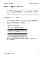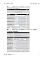
Task 6: Configuring prot ect ion
Chapt er 6: Configurat ion and alignm ent
6- 54
phn- 2513_004v000 ( Oct 2012)
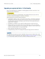
Configuring 1+1 Hot Standby links
Before configuring CMUs which are part of a 1+1 Hot Standby link, attach labels to each
CMU specifying IP Address, Site Name and Primary or Secondary status. Make it very
clear which site is required to transmit on the High side of the FDD frequency plan and
which is required to transmit at the low side.
Depending on the configuration, a CMU labelled Primary must eventually be connected to
one of the following:
•
The ODU which is connected to the arm of the coupler labelled Main.
•
The ODU which is connected to the antenna with the highest gain.
•
The left hand transceiver in an IRFU.
For background information, see
1+1 Hot Standby link protection
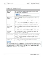
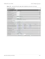
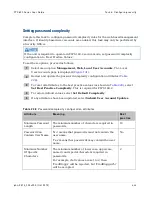
Before configuring the CMUs, ensure that the following information is known.
•
Which CMU is to be configured as Primary and which unit is to be configured as
Secondary. This is controlled by the Primary Secondary Mode attribute.
•
Whether the end is to be installed with one or two antennas. This is controlled by the
Number of Antennas attribute.
•
Whether the method of connection to the Ethernet switch is via Fiber-Y. This is
controlled by the Fiber-Y attribute. (see
Network configurations for 1+1
for details about Fiber-Y).
•
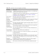
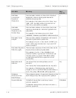
Whether the Primary Recovery feature should be enabled and if so, the value of
Primary Recovery Period. If the Primary has become Inactive for any reason, for
example a previous fault, this feature automatically forces the Primary to become
active again if it has been fault free for a configurable period of time defined by the
Primary Recovery Period. This only needs to be configured on the CMU configured as
Secondary.
•
Whether an Ethernet port down alert is required on each protection switch. This is
controlled by the Protection Switch Alert attribute. Enabling this feature is only of
benefit in complex networks, for example where a 1+1 Hot Standby link forms part of a
ring network architecture. This should normally remain disabled.
•
Whether Receive Diversity is to be enabled (see
Planning for Receive Diversity
for planning of this feature). This is controlled by the protection attribute.
•
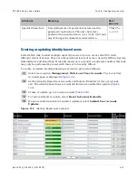
If Receive Diversity is to be enabled, ensure that the values for the Rx Diversity TPID
(Tag Protocol Identifier) and the Rx Diversity VID (VLAN identifier) are known.
Summary of Contents for PTP 800 Series
Page 1: ...Cambium PTP 800 Series User Guide System Release 800 05 02 ...
Page 40: ...Licensing requirements About This User Guide 10 phn 2513_004v000 Oct 2012 ...
Page 232: ...Limit of liability Chapter 3 Legal information 3 22 phn 2513_004v000 Oct 2012 ...
Page 322: ...Radiation hazard assessm ent Chapter 4 Reference information 4 90 phn 2513_004v000 Oct 2012 ...
Page 428: ...Replacing IRFU components Chapter 5 Installation 5 106 phn 2513_004v000 Oct 2012 ...
Page 630: ...Using recovery mode Chapter 7 Operation 7 78 phn 2513_004v000 Oct 2012 ...

